

-
Products -PCBA Manufacturing RF Connectors RF Cable Assemblys Embedded Antennas External Antennas Positioning Chips and Modules
RF Connectors

RF Cable Assemblys
Embedded Antennas
External Antennas
Positioning Chips and Modules


 Language


Language


In the rapidly evolving field of unmanned aerial vehicles (UAVs), reliable navigation is the cornerstone of safe and efficient operation. Global Navigation Satellite System (GNSS) antennas serve as the critical interface between UAVs and satellite constellations, enabling precise positioning, navigation, and timing (PNT) data. Unlike conventional GNSS antennas used in stationary or ground-based applications, those integrated into UAVs must withstand unique environmental stresses, including high vibration, rapid altitude changes, and exposure to diverse weather conditions. This analysis explores the technical specifications of GNSS UAV antennas, focusing on how PCB design parameters are optimized to meet the rigorous demands of aerial operations, ensuring consistent performance across dynamic mission profiles.
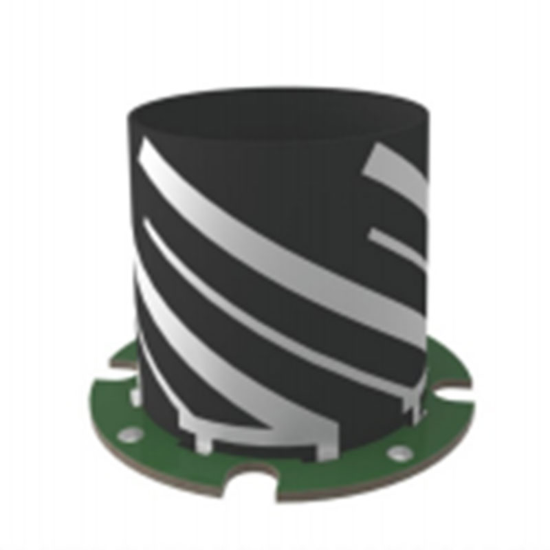
At the core of any GNSS UAV antenna lies a printed circuit board (PCB) constructed from FR4, a glass-reinforced epoxy laminate. FR4’s selection is driven by its exceptional balance of mechanical rigidity, electrical stability, and cost-effectiveness—attributes that are particularly valuable in UAV design, where weight and durability are paramount. For UAVs, which rely on multiple satellite constellations (e.g., GPS, GLONASS, Galileo, BeiDou) operating across frequencies ranging from 1176 MHz (L5 band) to 1602 MHz (L1 band), the dielectric constant of FR4 (approximately 4.4) is critical. This property ensures that the antenna’s radiating elements maintain consistent impedance across these bands, enabling seamless switching between constellations to maintain positioning accuracy even in challenging environments, such as urban canyons or remote areas with limited satellite visibility.
The 35μm copper thickness of the PCB plays a dual role in UAV antenna performance: enhancing conductivity while managing weight. Copper is the primary conductor for the antenna’s feed network and radiating patches, and its thickness directly influences signal loss. A 35μm layer provides sufficient conductivity to minimize ohmic losses in high-frequency signals, which is essential for UAVs operating at altitudes where signal strength can fluctuate. Additionally, this thickness strikes a balance between performance and weight—a key consideration for UAVs, where excess weight reduces flight time and maneuverability. Thicker copper would improve conductivity but add unnecessary mass, while thinner layers risk increased resistance and signal degradation. For multi-constellation antennas, which require complex feed networks to handle multiple frequencies, the uniformity of the copper layer is equally important. Variations in thickness can create impedance mismatches between frequency bands, leading to signal reflections and reduced efficiency.
Board thickness is specified at 1.6mm, a dimension that influences both the antenna’s radiation pattern and its mechanical resilience. In UAV antennas, which are often mounted on the drone’s frame or wing, the distance between the radiating patch and the ground plane (dictated by board thickness) determines the antenna’s gain and beamwidth. A 1.6mm thickness optimizes the radiation pattern for aerial use, ensuring a broad enough beamwidth to track satellites across the sky as the UAV pitches, rolls, and yaws during flight. This is critical for maintaining continuous positioning data, as even momentary signal loss can compromise navigation, especially in autonomous UAVs. Mechanically, the 1.6mm thickness provides sufficient rigidity to withstand the vibration and turbulence encountered during flight. UAVs typically operate in dynamic airflow conditions, and a thin or flexible PCB could deform under stress, altering the antenna’s resonant frequency and disrupting signal reception.
The minimum hole size of 0.2mm and minimum line width and spacing of 0.15mm reflect the precision required to integrate advanced components into compact UAV antenna designs. UAVs have limited space for onboard electronics, and these tight tolerances enable the miniaturization of the antenna while incorporating essential components such as filters, amplifiers, and phase shifters. Smaller holes (vias) facilitate dense interconnections between layers in multi-layer PCBs, allowing for the integration of bandpass filters that suppress interference from other UAV systems, such as communication radios or LiDAR sensors, which can operate in adjacent frequency bands. Narrow line widths and spacing enable the design of compact matching networks that tune the antenna to multiple GNSS frequencies without increasing the PCB footprint. This miniaturization is particularly valuable for small UAVs, such as consumer drones or inspection UAVs, where space is at a premium. However, these tight tolerances demand advanced manufacturing techniques, such as laser drilling and high-precision etching, to avoid defects like short circuits or open connections—failures that could lead to navigation errors or UAV (loss of control) during flight.
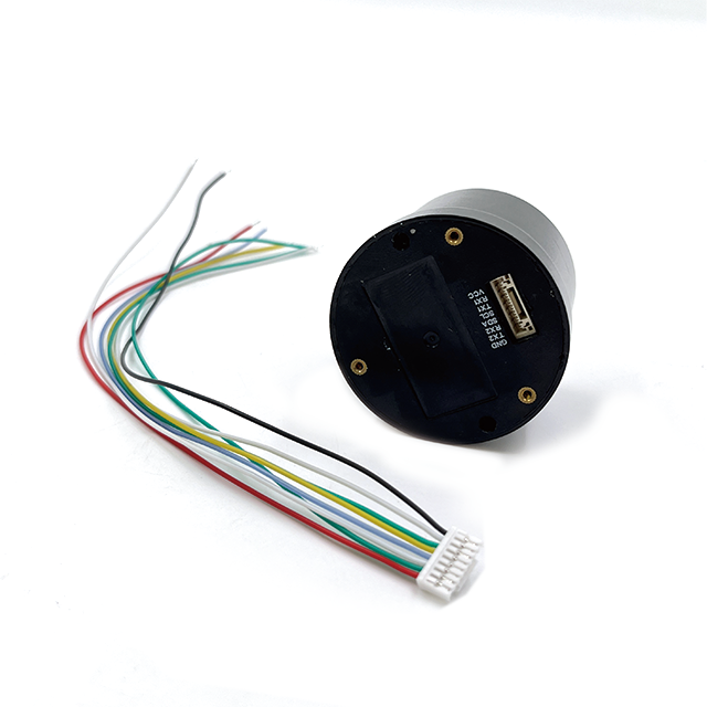
The active nature of the antenna—incorporating a low-noise amplifier (LNA) directly on the PCB—is essential for UAVs operating in environments with weak signals. GNSS signals reaching the Earth’s surface are already weak (around -130 dBm), and UAVs flying at low altitudes may face additional attenuation from obstacles like trees or buildings. The LNA amplifies these signals before they reach the UAV’s receiver, but its performance is heavily dependent on the PCB design. The FR4 material’s low loss tangent minimizes dielectric losses that could introduce noise, while the precise line spacing prevents crosstalk between the LNA and the antenna’s radiating elements. For UAVs, which often carry other electronic systems generating electromagnetic interference (EMI), this isolation is critical. The LNA must operate with a noise figure below 1 dB to avoid corrupting weak signals, and the PCB’s layout—optimized using the specified line widths and spacing—ensures that EMI from motors, batteries, or communication modules does not degrade the amplifier’s performance.
Lead-free HASL surface finishing enhances the antenna’s reliability in the harsh environments encountered by UAVs. HASL provides a solderable surface for mounting the LNA, connectors, and other components, ensuring strong mechanical bonds that withstand vibration during flight. Lead-free HASL also complies with RoHS regulations, making the antenna suitable for global markets and reducing environmental impact—a key consideration for commercial and industrial UAV operators. Additionally, the solder layer protects the copper traces from oxidation, which is particularly important for UAVs used in outdoor applications. Drones often operate in humid or dusty environments, and oxidized copper would increase resistance in the feed network, leading to signal loss. For UAVs deployed in agriculture or search-and-rescue missions, where downtime is costly, this protection extends the antenna’s lifespan and reduces maintenance requirements.
The board size of 43.5mm x 25mm x 1.6mm is tailored to the space constraints of UAVs while maintaining performance. This compact form factor allows the antenna to be mounted in strategic locations—such as the drone’s top surface or undercarriage—without obstructing sensors, cameras, or propellers. For example, a lightweight antenna of this size can be integrated into the frame of a foldable consumer drone, where space is extremely limited. Despite its small size, the antenna’s performance is optimized through careful design: the ground plane occupies a significant portion of the PCB, providing shielding against EMI from the UAV’s internal electronics and ensuring a unidirectional radiation pattern focused skyward. This design minimizes interference from the drone’s body while maximizing satellite visibility, which is critical for maintaining accuracy in low-visibility conditions.
The availability of 2-layer, 4-layer, or multi-layer PCBs offers flexibility to address the diverse needs of UAV applications. A 2-layer PCB may suffice for basic consumer drones focused on GPS-only navigation, with the top layer housing the radiating patch and the bottom layer serving as a ground plane. However, industrial UAVs requiring multi-constellation support and enhanced EMI protection benefit from 4-layer or multi-layer designs. These configurations allow for dedicated layers for power distribution, shielding, and filter circuits. For example, a 4-layer PCB can include a separate layer for the LNA’s power supply, isolating it from digital noise generated by the UAV’s flight controller. This is particularly important for UAVs used in precision agriculture or infrastructure inspection, where centimeter-level positioning accuracy is required. Multi-layer designs also enable the integration of frequency-selective surfaces (FSS) to block interference from 5G or Wi-Fi signals, which operate in bands adjacent to GNSS frequencies.
Surface roughness (Rz 2.5 or Rz 3.0) is a critical parameter for maintaining signal integrity in high-frequency UAV antennas. At GNSS frequencies, the skin effect causes signal current to flow near the surface of the copper traces, and a rough surface increases the effective resistance, leading to signal loss. For UAVs operating at the edge of satellite coverage, such as in remote areas, even minor losses can degrade positioning accuracy. A smoother surface (Rz 2.5) reduces these losses, making it preferable for applications requiring high precision. Manufacturers achieve this by using advanced polishing techniques during PCB fabrication, ensuring that the copper layer’s surface is uniform. This is especially important for multi-frequency antennas, where current distribution varies across bands—irregularities in surface roughness could disproportionately affect higher frequencies, such as the L5 band (1176 MHz), which is increasingly used for its improved accuracy.
Solder mask color (green, blue, black) and silkscreen color (white, yellow) have practical implications beyond aesthetics in UAV antennas. The solder mask protects the copper traces from physical damage during UAV assembly and maintenance, and its color can influence thermal management. Darker colors like black absorb more heat, which can be beneficial in cold environments but problematic in hot climates. For UAVs operating in desert regions or during summer months, a lighter color (green or blue) may help dissipate heat, preventing the LNA from overheating and degrading performance. The silkscreen, used for component labeling, must be highly visible to facilitate quick repairs in the field. White silkscreen on a green or blue mask offers high contrast, allowing technicians to identify components easily—an important feature for UAV operators working in remote locations with limited tools.
Thermal conductivity of 1.0 W/mK or 1.5 W/mK is critical for managing heat in UAV antennas, which are often enclosed in compact housings with limited airflow. The LNA generates heat during operation, and excessive temperatures can increase its noise figure, reducing signal sensitivity. A higher thermal conductivity (1.5 W/mK) allows heat to transfer from the LNA to the PCB’s ground plane and then to the UAV’s frame, which acts as a heat sink. This is particularly important for UAVs operating in hot environments or during extended flights, where heat buildup can compromise performance. In multi-layer PCBs, thermal vias—small holes filled with conductive material—are used to enhance heat transfer from the LNA’s mounting pad to the ground plane, further improving thermal management. For autonomous UAVs on long missions, such as pipeline inspections, reliable thermal performance ensures consistent positioning accuracy throughout the flight.
The UL94 V-0 flame retardant rating enhances the safety of UAVs, which often carry batteries and other flammable components. In the event of a electrical malfunction, the PCB’s ability to resist ignition and self-extinguish within 10 seconds reduces the risk of fire, protecting both the UAV and its surroundings. This is particularly important for UAVs used in urban areas, near wildlife, or in industrial facilities where fire safety is regulated. The UL94 V-0 rating ensures compliance with international safety standards, making the antenna suitable for commercial and industrial applications.
The operating temperature range of -40°C to 105°C and storage temperature range of -40°C to 125°C ensure that the antenna performs reliably in the diverse environments UAVs encounter. From cold-weather missions in polar regions to hot desert operations, temperature fluctuations can cause PCB materials to expand or contract. FR4’s low coefficient of thermal expansion minimizes these effects, preventing warping that could alter the antenna’s resonant frequency. Components like the LNA are also selected to operate within these ranges, with temperature-compensated circuits to maintain performance. For example, in freezing temperatures, the LNA’s gain might decrease slightly, but the PCB’s stable dielectric properties ensure that the antenna’s impedance remains matched, mitigating signal loss.
RoHS compliance (Yes/No) reflects the antenna’s alignment with global environmental regulations, which is increasingly important for UAV manufacturers and operators. RoHS-compliant antennas avoid hazardous substances like lead and cadmium, reducing environmental impact and ensuring access to markets with strict regulations, such as the European Union and China. For commercial UAV companies, RoHS compliance is not only a legal requirement but also a selling point for environmentally conscious customers.
Adherence to IPC-A-600 Class 2 standards guarantees the antenna’s quality and reliability, which is critical for UAVs where component failure can have serious consequences. IPC-A-600 Class 2 specifies rigorous requirements for conductor integrity, solder mask coverage, and hole quality, ensuring that the PCB can withstand the mechanical and electrical stresses of UAV operation. For example, the standard mandates minimal conductor spacing to prevent short circuits, which is essential for the dense, high-frequency circuits in multi-constellation antennas. Compliance with this standard provides UAV manufacturers with confidence that the antenna will perform consistently across thousands of flight hours.
In conclusion, the technical specifications of GNSS UAV antennas are meticulously engineered to balance performance, durability, and weight—key factors in aerial navigation. From the FR4 substrate and copper thickness to the thermal conductivity and compliance standards, each parameter is optimized to ensure reliable positioning data in dynamic and often harsh environments. As UAVs continue to expand into applications such as autonomous delivery, precision agriculture, and disaster response, the role of robust GNSS antennas becomes increasingly critical. By leveraging these technical specifications, manufacturers can produce antennas that enable UAVs to navigate with precision, safety, and efficiency, unlocking new possibilities for aerial technology.

 86 0755 2819 9597
Lucy Yang | lucy.y@toxutech.com
Nicole Li | nicole@toxutech.com
Dotty Zhao | sales04@toxutech.com
Global Business Director / Sales Team / Global Operations


 En
En Cn
Cn Korean
 Home >


