

-
Products -PCBA Manufacturing RF Connectors RF Cable Assemblys Embedded Antennas External Antennas Positioning Chips and Modules
RF Connectors

RF Cable Assemblys
Embedded Antennas
External Antennas
Positioning Chips and Modules


 Language


Language


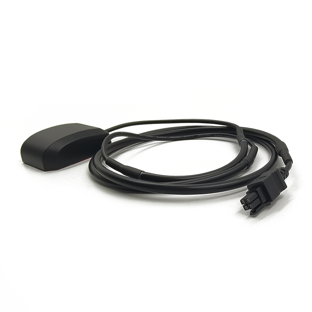
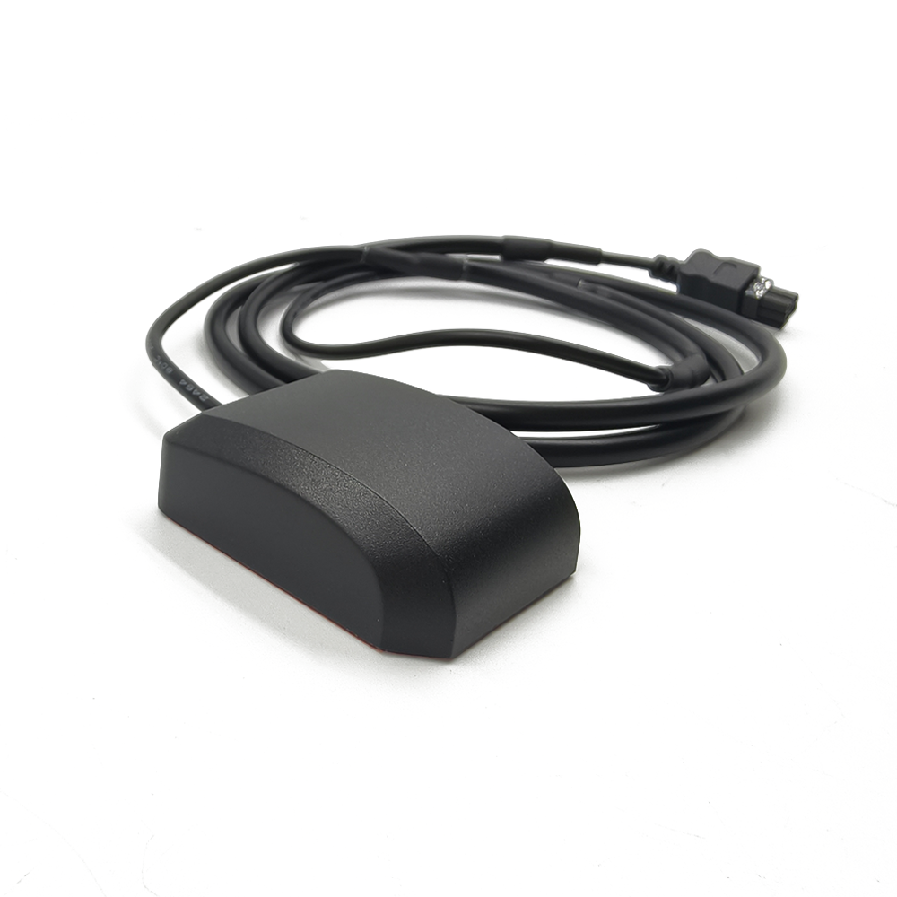
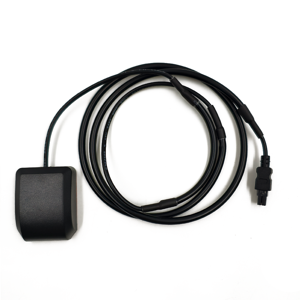

In the ecosystem of high-precision positioning, the GNSS RTK external antenna serves as a critical interface between satellite signals and the receiver, playing a pivotal role in determining the overall accuracy and reliability of the system. Unlike internal antennas, which are constrained by the physical limitations of the receiver’s enclosure, external antennas are engineered to optimize signal capture, minimize interference, and withstand harsh environmental conditions—all essential for real-time kinematic (RTK) applications requiring centimeter-level precision. This analysis delves into the technical specifications of a GNSS RTK external antenna, exploring how its design features, from connectivity and material selection to frequency tuning and gain characteristics, enable it to support the demanding requirements of RTK receivers in fields such as surveying, construction, and precision agriculture.
At the forefront of the antenna’s design is its 4Pin Custom Connector, a specialized interface that ensures secure and reliable electrical connectivity with the RTK receiver. Unlike standard connectors such as TNC or MCX, a custom 4Pin design is tailored to the specific power and signal requirements of RTK systems, often integrating power, ground, and two signal lines to support differential data transmission. This customization minimizes signal loss by optimizing the pin layout for the antenna’s low-noise amplifier (LNA) and filter circuitry, ensuring that the delicate balance between power delivery and signal integrity is maintained. The 4Pin configuration also enhances mechanical stability, with a robust locking mechanism that prevents accidental disconnection— a critical feature in field operations where vibration, weather, or physical contact could disrupt the link. For RTK systems, where even momentary signal loss can delay ambiguity resolution or degrade positioning accuracy, this reliability is indispensable. Additionally, the custom nature of the connector allows manufacturers to integrate surge protection or electrostatic discharge (ESD) safeguards directly into the interface, shielding sensitive receiver components from voltage spikes common in outdoor environments.
The use of ABS (Acrylonitrile Butadiene Styrene) as the antenna’s housing material reflects a deliberate choice to balance durability, weight, and cost-effectiveness. ABS is renowned for its impact resistance, making it ideal for external antennas subjected to rough handling, drops, or collisions in construction zones or agricultural fields. Unlike metal enclosures, which can interfere with RF signals or add unnecessary weight, ABS is non-conductive and lightweight (typically around 1.05 g/cm³), ensuring that the antenna can be mounted on survey poles, vehicle roofs, or drone frames without compromising stability. Its resistance to moisture, chemicals, and UV radiation further enhances its suitability for outdoor use, preventing degradation from rain, fertilizer exposure, or prolonged sunlight. For RTK antennas deployed in remote areas, where maintenance access is limited, the longevity of ABS ensures consistent performance over years of operation. The material’s moldability also allows for complex housing designs that integrate features like integrated mounting flanges, cable management channels, or aerodynamic profiles—important for minimizing wind resistance on moving platforms like tractors or drones.
Linear polarity is a defining electrical characteristic of this antenna, distinguishing it from circularly polarized alternatives and influencing its performance in specific RTK scenarios. Linear polarization aligns the antenna’s reception with the vertical or horizontal orientation of the incoming satellite signal’s electric field. While circularly polarized antennas are often preferred for general navigation due to their ability to receive signals from any polarization angle, linear polarization offers advantages in RTK applications where signal strength and consistency are prioritized. For example, in open-sky environments—common in agriculture or large construction sites—linear polarization can provide higher signal-to-noise ratios (SNR) when aligned with the satellite’s signal orientation, which is typically linear for many GNSS constellations. This alignment maximizes signal capture efficiency, ensuring that even weak signals (often around -160 dBm at ground level) are amplified sufficiently by the LNA. However, linear polarization requires careful mounting to maintain alignment; a misaligned antenna (e.g., tilted or rotated) can experience significant signal attenuation. To mitigate this, RTK systems often pair linear antennas with adjustable mounts, allowing surveyors or operators to optimize orientation based on satellite constellation geometry. In applications like marine surveying, where the antenna may pitch or roll, some systems integrate gyroscopic stabilization to maintain polarization alignment, preserving signal integrity.
The frequency range of L1 C/A Band (1575.42 MHz) focuses the antenna’s performance on the primary civilian GPS band, a strategic choice for cost-sensitive RTK applications that prioritize compatibility and reliability. The L1 C/A (Coarse/Acquisition) band is the most widely used GNSS frequency, supported by GPS, Galileo (E1), and BeiDou (B1), ensuring interoperability across multiple constellations. While multi-frequency antennas offer advantages in mitigating ionospheric delays, single-frequency L1 antennas remain popular in applications where cost is a factor or where ionospheric activity is low (e.g., mid-latitude regions). For RTK systems, the L1 band provides a stable foundation for carrier phase measurements, with a wavelength of approximately 19 cm that enables sub-centimeter resolution when combined with precise ambiguity resolution. The antenna’s design is optimized for this frequency, with a radiating element (typically a patch or helical design) tuned to resonate at 1575.42 MHz, ensuring maximum energy transfer from the electromagnetic field to the receiver. This tuning minimizes return loss, a key metric for efficient signal capture, and is achieved through precise dimensions of the radiating element and its distance from the ground plane—both critical parameters in the antenna’s PCB design.
An impedance of 50Ω is a standard in RF engineering and ensures seamless integration between the antenna and the RTK receiver’s front-end circuitry. Impedance matching is essential to prevent signal reflections, which can cause standing waves, power loss, and phase distortions—all of which degrade the accuracy of carrier phase measurements. The antenna’s feed network, including the LNA and cable, is designed to maintain 50Ω impedance throughout the signal path, from the radiating element to the receiver’s input. This consistency is particularly important for RTK systems, where phase stability directly impacts ambiguity resolution. Even minor mismatches (e.g., 50Ω antenna connected to a 75Ω cable) can introduce phase errors that accumulate over time, leading to positioning inaccuracies. To verify impedance matching, manufacturers measure the antenna’s return loss, with a return loss of -10 dB or better indicating that 90% of the signal is transmitted to the receiver (vs. reflected). This level of performance ensures that the full gain of the antenna is effectively utilized, maximizing the SNR for weak satellite signals.
The VSWR (Voltage Standing Wave Ratio) of ≤2.0 is a key indicator of the antenna’s efficiency and impedance matching. VSWR measures the ratio of the maximum to minimum voltage of the standing wave created by reflected signals, with a VSWR of 1.0 representing perfect matching (no reflection). A VSWR of ≤2.0 is considered acceptable for RTK applications, indicating that reflection losses are limited to approximately 10% or less. This ensures that most of the captured signal power is transferred to the receiver, rather than being wasted or causing interference within the antenna. High VSWR (e.g., >3.0) can lead to overheating of the LNA, increased noise, and reduced sensitivity—all detrimental to RTK performance. The antenna achieves this low VSWR through careful design of the radiating element, ground plane, and feed network. For example, the ground plane size is optimized to prevent edge reflections that could disrupt the standing wave pattern, while the feed point is precisely positioned to balance the antenna’s input impedance. Environmental factors like temperature or moisture can affect VSWR, but the use of ABS housing and stable dielectric materials in the PCB ensures that VSWR remains within the specified range across the operating temperature spectrum.
A gain of 28 dBi positions this antenna as a high-performance option, providing significant amplification of weak satellite signals to support RTK’s demanding accuracy requirements. Gain in antennas refers to the ability to focus radiation in a specific direction, with higher gain indicating a more directional pattern. A 28 dBi gain is relatively high for an RTK external antenna, suggesting a narrow beamwidth that concentrates reception toward the sky, where GNSS satellites reside. This directional focus minimizes interference from ground-based sources (e.g., cellular towers, industrial equipment) and enhances the signal strength from satellites, which is critical for maintaining lock in challenging environments like light tree cover or urban fringes. The gain is achieved through a combination of the antenna’s radiating element design (e.g., a stacked patch or array configuration) and the integrated LNA, which amplifies the signal before it travels through the cable to the receiver. It is important to note that gain is a trade-off with beamwidth: a higher gain antenna has a narrower field of view, requiring more precise alignment to avoid missing low-elevation satellites. For RTK systems, which rely on multiple satellites for positioning, this means the antenna must be mounted with a clear view of the horizon, and in some cases, paired with a low-gain backup antenna to ensure coverage during brief obstructions.
The operating voltage range of 3.3V to 5V ensures compatibility with a wide range of RTK receivers, which may use different power supplies based on their design or application. This flexibility is crucial in field operations, where receivers may be powered by batteries (3.3V) or vehicle systems (5V). The antenna’s LNA is designed to operate efficiently across this range, maintaining a low noise figure (typically <1 dB) to avoid corrupting weak signals. Voltage stability is also important; fluctuations outside this range can cause the LNA to enter non-linear operation, introducing distortion or reducing gain. To address this, many RTK antennas include voltage regulation circuitry that stabilizes the input voltage, protecting the LNA and ensuring consistent performance even when the receiver’s power supply varies (e.g., during battery discharge). This regulation is particularly important for portable RTK systems used in surveying, where battery life is critical—efficient power usage (often <100 mA at 5V) extends operating time between charges.
The compact dimensions of 49.5mm x 38mm x 16.4mm make this antenna ideal for space-constrained RTK applications, without sacrificing performance. In contrast to larger survey antennas, which prioritize gain and beamwidth, this compact design is tailored for integration into portable devices, drones, or vehicle-mounted systems where size and weight are limiting factors. For example, in drone-based RTK mapping, the small form factor reduces aerodynamic drag and allows for easier integration with payloads like cameras or LiDAR sensors. Despite its size, the antenna’s performance is optimized through advanced PCB design, with miniaturized components and efficient use of space. The ground plane, while smaller than in larger antennas, is still sized to provide adequate shielding and signal reflection, ensuring that the radiating element operates at its designed frequency. The compact housing also reduces wind resistance, making it suitable for high-speed applications like vehicle-mounted RTK for road surveying, where stability at speed is essential.
The operating temperature range of -40°C to +85°C underscores the antenna’s ruggedness, ensuring reliable performance in extreme environments. From polar surveying missions to desert construction sites, temperature fluctuations can affect both the antenna’s mechanical and electrical properties. At low temperatures, ABS housing remains impact-resistant, while the PCB’s dielectric materials (e.g., FR4) maintain stable electrical characteristics, preventing shifts in resonant frequency. The LNA’s performance is also temperature-compensated, with circuitry that adjusts bias currents to maintain low noise figures even as temperatures drop. At high temperatures (up to 85°C), the antenna’s components resist thermal degradation: the LNA avoids thermal runaway, the cable’s insulation remains intact, and the ABS housing does not warp or soften. This thermal resilience is critical for RTK systems deployed in unregulated environments, such as agricultural fields exposed to direct sunlight or industrial sites with heat-generating equipment.
Integration with RTK receivers is a key consideration, and this antenna’s specifications are designed to complement the receiver’s capabilities. The high gain (28 dBi) compensates for cable losses, which can be significant in systems where the antenna is mounted remotely from the receiver (e.g., on a survey pole 10 meters away). For example, a 10-meter coaxial cable may introduce 3–4 dB of loss at L1 frequency, but the antenna’s gain ensures that the signal reaching the receiver remains strong enough for processing. The linear polarization, when aligned correctly, works with the receiver’s multi-constellation tracking to maximize the number of visible satellites, a key factor in reducing dilution of precision (DOP). The 50Ω impedance and low VSWR ensure that the receiver’s front-end circuitry operates efficiently, with minimal signal reflection that could corrupt phase measurements.
In precision agriculture, this antenna’s compact size and high gain make it well-suited for mounting on tractors or harvesters, where space is limited but accuracy is critical. Linear polarization, when aligned with the vertical, captures strong signals from overhead satellites, enabling RTK-guided machinery to maintain centimeter-level row spacing. The ABS housing resists damage from crop debris or contact with farm equipment, ensuring longevity in harsh conditions. The 4Pin connector’s reliability prevents signal loss during bumpy rides, maintaining continuous RTK corrections for seamless operation.
In drone surveying, the antenna’s small form factor and lightweight design reduce payload strain, extending flight time. The high gain compensates for signal blockages caused by the drone’s body or propellers, ensuring that even when the antenna is partially obscured, enough signal is captured to maintain RTK lock. Linear polarization, combined with the drone’s stable flight attitude, ensures consistent signal reception, while the ABS housing withstands the vibrations and temperature changes encountered during flight.
In construction, the antenna’s ruggedness and wide temperature range make it suitable for mounting on graders, excavators, or survey stakes. The 4Pin connector’s secure locking mechanism prevents disconnection during heavy machinery operation, while the high gain ensures reliable signal capture even near tall structures that may block low-elevation satellites. The linear polarization, when adjusted to account for the antenna’s tilt on uneven terrain, maintains signal strength, supporting real-time positioning for precise grading or foundation work.
Despite its strengths, the antenna has limitations that users must consider. The linear polarization requires careful mounting alignment; misalignment by 30 degrees can reduce signal strength by 50% (3 dB), potentially delaying ambiguity resolution. The single-frequency (L1) design leaves it vulnerable to ionospheric delays in high-latitude regions, where multi-frequency antennas would provide better accuracy. The compact size, while beneficial for portability, results in a narrower beamwidth, increasing the risk of signal loss if the antenna is obstructed by obstacles like trees or buildings.
To address these limitations, manufacturers often recommend pairing the antenna with a high-quality coaxial cable (e.g., low-loss RG-58 or LMR-195) to minimize signal attenuation. They also provide mounting guides to ensure proper polarization alignment, often including bubble levels or alignment marks on the housing. For applications in ionospherically active regions, combining the antenna with a receiver that supports PPP (Precise Point Positioning) can mitigate errors, leveraging global correction data to supplement RTK.
In conclusion, the GNSS RTK external antenna, with its custom connectivity, rugged ABS housing, linear polarization, and high gain, is a specialized component engineered to meet the exacting demands of high-precision positioning. Its design balances performance, durability, and compactness, making it suitable for diverse applications from agriculture to drone surveying. By optimizing signal capture, minimizing interference, and withstanding harsh environments, this antenna enables RTK receivers to deliver the centimeter-level accuracy that has become indispensable in modern engineering, agriculture, and geospatial mapping. As RTK technology continues to evolve, the role of such antennas will only grow, bridging the gap between satellites and receivers to unlock new possibilities in precision and efficiency.

 86 0755 2819 9597
Lucy Yang | lucy.y@toxutech.com
Nicole Li | nicole@toxutech.com
Dotty Zhao | sales04@toxutech.com
Global Business Director / Sales Team / Global Operations


 En
En Cn
Cn Korean
 Home >


