

-
Products -PCBA Manufacturing RF Connectors RF Cable Assemblys Embedded Antennas External Antennas Positioning Chips and Modules
RF Connectors

RF Cable Assemblys
Embedded Antennas
External Antennas
Positioning Chips and Modules


 Language


Language


In the precise and demanding world of Real-Time Kinematic (RTK) positioning, where centimeter-level accuracy is the paramount objective, every component in the signal chain is critical. While advanced receiver algorithms and robust communication links receive significant attention, the foundation of the entire system is the GNSS RTK external antenna. This component is the first and most crucial interface between the satellite constellation and the processing engine. Its role is not merely to receive signals but to do so with an unparalleled degree of fidelity, stability, and purity, acting as the gatekeeper of data integrity for high-precision applications.
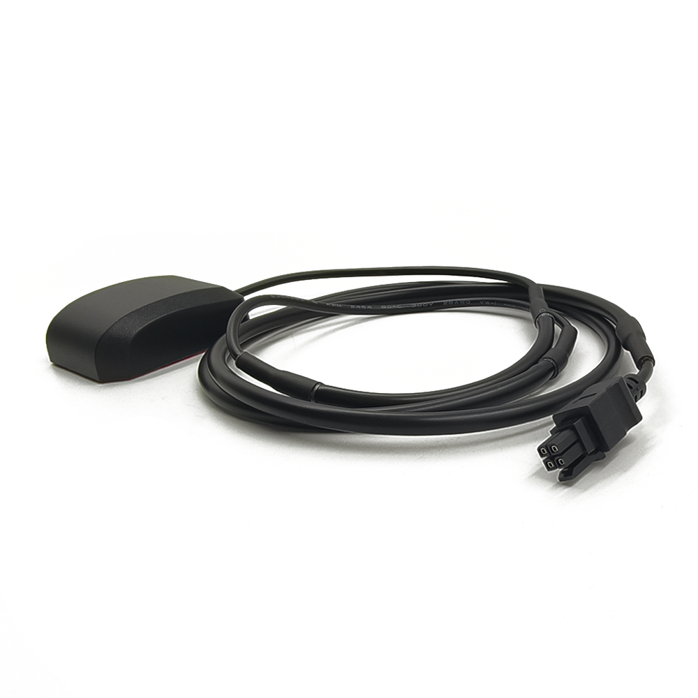
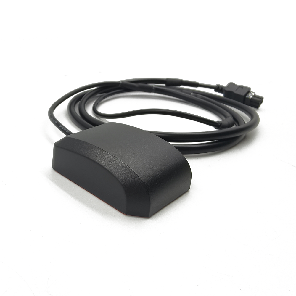
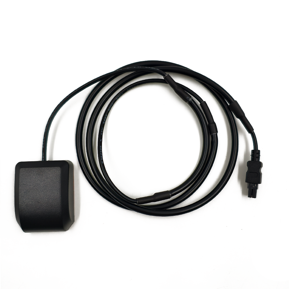
An external antenna, in the context of RTK, is defined by its placement and purpose. It is a standalone unit, typically mounted on a fixed pole, tripod, or the roof of a vehicle, and connected to the GNSS receiver via a coaxial cable. This external placement is a deliberate and necessary design choice, separating the antenna from the electronic noise, physical obstructions, and compromising environments that plague internal antennas. Its sole purpose is to provide the cleanest possible signal to the receiver, enabling the complex mathematical processes of carrier-phase measurement and ambiguity resolution that underpin RTK technology.
The fundamental value proposition of an RTK-grade external antenna lies in its ability to mitigate error sources at the point of reception, before they can ever corrupt the data stream. The two most pernicious enemies of high-precision GNSS are multipath interference and electronic noise. Multipath occurs when satellite signals arrive at the antenna not directly, but after reflecting off surfaces like the ground, buildings, or water. These reflected signals are delayed, creating errors that can easily swamp the centimeter-level measurements RTK strives for. A standard antenna might accept these signals; an RTK antenna is engineered to reject them.
Furthermore, the sensitive process of measuring the phase of the carrier wave—the key to RTK's precision—requires exceptional phase stability. The electrical point from which the signal is measured, known as the phase center, must remain constant regardless of the direction of the incoming signal or environmental changes like temperature. Any variation in this phase center introduces a direct error into the measurement. RTK external antennas are meticulously designed and calibrated to have a stable and well-characterized phase center.
These antennas are the bedrock of both base stations and rovers in an RTK system. For a base station, which calculates corrections based on a known position, any error in its measurements is transmitted to and incorporated by all rovers, corrupting an entire network. Therefore, the base station antenna must be of the highest quality, often employing advanced techniques like choke rings to ensure its data is pristine. For a rover, such as on an agricultural tractor or surveyor's pole, a high-performance external antenna provides faster initialization times, more robust maintenance of a "fixed" solution, and reliable operation in challenging environments.
In essence, the GNSS RTK external antenna is a specialized instrument, a significant step above consumer-grade GNSS antennas. It is a product of sophisticated electromagnetic engineering, precision manufacturing, and rigorous calibration. Its overview reveals a component that is not a passive accessory but an active and critical contributor to the accuracy and reliability of the entire RTK system, enabling the automation and precision that define modern surveying, agriculture, construction, and science.
The design and construction of a GNSS RTK external antenna is a meticulous process focused on achieving one goal: the preservation of signal integrity. Every material, geometric shape, and electronic component is chosen and arranged to maximize desired signal reception and minimize all sources of error. This results in a device that is both a sophisticated electromagnetic tool and a ruggedized piece of field equipment.
Core Radiating Element: The Patched Array
At the heart of most high-precision external antennas is a stacked-patch design. This involves two or more concentric patch antenna elements, separated by layers of dielectric substrate.
Multi-Frequency Operation: The larger, lower patch is tuned to lower frequency bands (e.g., GPS L2, L5; Galileo E5a, E5b; BeiDou B2, B3), while the smaller, upper patch is tuned to higher frequency bands (e.g., GPS L1; Galileo E1; BeiDou B1). This allows each patch to operate near its optimal resonance point, providing efficient performance across the entire GNSS spectrum without severe compromise.
Feeding Mechanism: High-end antennas often use aperture-coupled or slot-coupled feeds. Instead of a direct probe that can introduce unwanted inductance, the RF energy is coupled to the radiating patch through a slot or aperture in a ground plane. This technique provides superior impedance matching, broader bandwidth, and reduces parasitic radiation, leading to a cleaner phase response.
The Ground Plane and Multipath Mitigation Structures
The ground plane is a critical part of the antenna system, serving as an electrical reference and shaping the radiation pattern.
Flat Ground Plane: A standard feature, it provides a basic level of multipath rejection for signals arriving from below the horizon.
Choke Ring Ground Plane (The Gold Standard): For the highest performance, many geodetic and base station antennas incorporate a choke ring structure. These are concentric, circular troughs machined into a metal base. Each ring acts as a corrugated surface that presents a high impedance to surface currents. This effectively "chokes" or prevents currents from multipath signals (which travel as surface waves along the ground plane) from reaching the radiating element. The depth of the rings is carefully designed to be a quarter-wavelength at the target frequency, creating a resonant structure that rejects multipath.
Phase Center Stability: The Benchmark of Precision
For RTK, the stability of the antenna's phase center is non-negotiable. This is the electrical point from which measurements are referenced.
Mechanical Construction: The antenna is built with extreme mechanical symmetry and precision. The use of stable materials (e.g., machined aluminum body, ceramic substrates) ensures that the physical structure does not deform with temperature changes, which would shift the phase center.
Calibration: Every model of high-precision antenna is individually characterized in an anechoic chamber. Its Phase Center Offset (PCO)—the vector between its physical reference point and its electrical phase center—and Phase Center Variation (PCV)—how the phase center moves with different satellite elevations and azimuths—are meticulously measured for every frequency. These values are published in standardized ANTEX (ANTenna EXchange) format files. Using these calibrations in post-processing or modern RTK engines is essential to eliminate antenna-specific biases and achieve millimeter-level accuracy.
Integrated Active Components: LNA and Filtering
An RTK antenna is almost always an active antenna. It contains integral electronics:
Low-Noise Amplifier (LNA): This amplifier is placed immediately after the radiating element. Its purpose is to boost the extremely weak signals from space (around -130 dBm) before they suffer loss in the coaxial cable running to the receiver. A high-gain (26-40 dB), low-noise-figure (<2 dB) LNA is critical for preserving the Signal-to-Noise Ratio (SNR).
Bandpass Filters: SAW (Surface Acoustic Wave) or BAW (Bulk Acoustic Wave) filters are placed before the LNA. These are essential for rejecting powerful out-of-band interference from cellular, VHF, and WiFi transmitters, which could overload the sensitive LNA and receiver front-end.
Physical Construction and Environmental Sealing
Radome: The entire assembly is protected by a radome. This cover is made from a material that is virtually transparent to RF signals (e.g., high-grade polycarbonate or ceramic-filled plastic). It must be rugged to withstand impact and UV-resistant to prevent degradation from sun exposure.
Environmental Sealing: The unit is hermetically sealed to an IP67 or higher rating to prevent moisture, dust, and condensation from entering and damaging the internal components or detuning the antenna. This is crucial for reliable operation in all weather conditions.
Mounting and Connectors: The base features a robust mounting system (e.g., a 5/8"-11 thread standard for survey poles) designed for stability. The RF output typically uses a ruggedized TNC or N-type connector, which is more secure and weather-resistant than the smaller SMA connectors found on consumer devices.
In summary, the construction of an RTK external antenna is a holistic endeavor that blends advanced electromagnetic theory, precision mechanical engineering, and robust industrial design. It is a instrument where every detail, from the chemistry of the dielectric substrate to the sealing of the connector, is optimized to serve the singular goal of delivering a pristine signal.
The working principle of a GNSS RTK external antenna transcends simple signal reception. It functions as a highly selective spatial and spectral filter, actively shaping the reception of radio waves to maximize the desired direct signals and ruthlessly suppress sources of error. Its operation is governed by the principles of antenna theory, carefully engineered to support the fragile process of carrier-phase measurement.
Spatial Filtering: The Art of Directional Reception
The primary function of the antenna is to define a radiation pattern—a map of its sensitivity to signals arriving from different directions. The ideal pattern for an RTK antenna is highly directional in the upward hemisphere:
High Gain at High Elevation Angles: The antenna is designed to be most sensitive to signals arriving from directly overhead down to about 10-15 degrees above the horizon. This is where direct, line-of-sight satellite signals, which have traveled through the least amount of atmosphere and are least likely to be multipath, are located.
Rapid Gain Roll-Off at Low Elevation Angles: The sensitivity drops sharply for signals arriving from below 10 degrees. This is a key multipath mitigation strategy, as signals reflecting off the ground or nearby obstacles arrive at these low angles.
Deep Nulls Below the Horizon: The antenna is designed to be virtually deaf to signals arriving from below the horizon, which are almost exclusively multipath.
This shaped pattern is achieved through the combination of the radiating patch and the ground plane. The finite size of the ground plane is crucial; it acts as a baffle, blocking signals from below. In a choke ring antenna, the rings synthetically create an extremely deep null at the horizon through destructive interference of surface waves.
Phase Stability: The Heart of Precision
While spatial filtering deals with signal amplitude, the core of RTK relies on measuring signal phase. The antenna must preserve the geometric integrity of the incoming wavefront.
Consistent Electrical Path Length: The design ensures that the electrical path from the antenna's aperture to its output connector is identical for signals from all directions. Any variation would mean that the measured phase depends on the satellite's position, not just the geometric distance, introducing a devastating error.
Minimizing Phase Center Variation (PCV): A perfect antenna would have a phase center that is a fixed point in space. In reality, it moves slightly. The stacked-patch design, symmetric construction, and stable materials are all chosen to minimize this movement. The published PCV calibrations allow software to correct for the remaining, minimal variation.
Active Signal Conditioning: LNA and Filtering
The antenna's active components perform critical signal conditioning before the signal ever enters the cable.
Low-Noise Amplification (LNA): The LNA's primary role is to overcome cable loss. A long coaxial cable can attenuate the signal significantly. By amplifying the signal at the source, the LNA ensures that the signal arriving at the receiver is strong enough to be processed effectively, preserving the SNR. A high SNR is directly correlated with better tracking and lower measurement noise.
Front-End Filtering: The integrated bandpass filters are the gatekeepers. They create a "passband" that includes all GNSS frequencies (e.g., ~1160-1300 MHz for L5/L2 and ~1550-1610 MHz for L1) while aggressively rejecting all other frequencies. This is vital because powerful out-of-band signals from nearby radios, even if they don't jam the receiver, can cause intermodulation distortion or gain compression in the LNA, subtly degrading the amplification of the weak GNSS signals.
Multipath Rejection Mechanisms
The antenna employs multiple strategies to combat multipath:
Radiation Pattern: As described, the primary method is to not "listen" to the directions from which multipath arrives.
Right-Hand Circular Polarization (RHCP) Discrimination: GNSS satellites transmit RHCP signals. When a signal reflects off a surface, its polarization often reverses to Left-Hand Circular Polarization (LHCP) or becomes elliptical. The antenna is designed to be highly sensitive to RHCP and much less sensitive to LHCP, providing another layer of rejection for reflected signals.
Choke Rings: For premium antennas, the choke rings provide the most effective multipath suppression by preventing surface waves from ever exciting the radiator.
In essence, the working principle of the RTK external antenna is to act as a pre-processor. It doesn't just pass along raw RF energy; it selectively amplifies the good, filters out the bad, and ensures that the phase information embedded in the carrier wave is delivered to the receiver with the highest possible fidelity and geometric consistency. This clean, stable signal is the essential raw material that allows the receiver's algorithms to perform the magic of RTK.
The decision to use an external antenna for an RTK system is a commitment to performance. It offers a clear set of compelling advantages that are essential for achieving and maintaining high precision, but these benefits come with associated challenges that must be managed in system design and field operation.
Advantages:
Superior Multipath Rejection: This is the most significant advantage. The external placement and specialized design (especially choke rings) provide unmatched ability to suppress signals reflected from the ground, buildings, and other obstacles. This directly translates to lower measurement noise, faster and more reliable integer ambiguity resolution, and a higher percentage of time spent in a fixed RTK solution.
Optimal Positioning and Unobstructed Sky View: Being external allows the antenna to be placed in the optimal location for satellite reception—on a tripod, a pole, or the roof of a vehicle. This ensures a clear, unobstructed view of the sky, maximizing the number of satellites tracked and improving the geometry of the satellite constellation (lower DOP values), which enhances accuracy.
Immunity to Platform-Specific EMI: By being located outside and away from the device it serves, the antenna is isolated from the electromagnetic interference (EMI) generated by the receiver's own electronics, as well as from other systems on a vehicle or machine (e.g., engine control units, displays, other radios). This isolation is crucial for maintaining a high Signal-to-Noise Ratio (SNR).
Exceptional Phase Center Stability: The rigid, mechanically stable construction of external antennas ensures that their phase center characteristics are predictable and stable over time and temperature. This stability is a prerequisite for high-precision work, as any uncalibrated movement of the phase center introduces a direct error into the carrier-phase measurement.
Support for Long Cable Runs: The integrated high-gain LNA allows the antenna to be connected to the receiver via long coaxial cables (50-100 meters or more) without significant degradation of the SNR. This is essential for permanent base station installations where the receiver must be located indoors, away from the elements.
Challenges and Limitations:
Cost: High-precision external antennas are significantly more expensive than consumer-grade or internal antennas. The use of specialized materials (e.g., ceramic substrates, machined aluminum), complex manufacturing processes, and the requirement for individual calibration in an anechoic chamber all contribute to a high unit cost.
Size, Weight, and Wind Loading: Performance comes at the cost of bulk. Geodetic antennas with choke rings are large, heavy, and can act like a sail in windy conditions. This can introduce vibration into the mounting system, which is detrimental to precision measurement. It requires a robust and stable tripod or monument for installation.
Deployment Practicality and Portability: An external antenna is not an all-in-one device. It requires a separate receiver, a cable, and a mounting apparatus. This makes the system less portable and more cumbersome to set up and tear down compared to a device with an integrated antenna. It is susceptible to cable damage, connector wear, and requires careful handling.
Power Requirements: The active antenna requires power for its internal LNA. This power is typically supplied by the receiver through the coaxial cable (phantom power). This must be managed to ensure compatibility and places a small but additional power burden on the receiver system.
Calibration Dependency: To achieve the highest possible accuracy, the user must apply the correct antenna calibration data (PCO and PCV from an ANTEX file) in their processing software. Using the wrong calibration, or no calibration, can introduce errors of several centimeters, negating the benefits of the high-quality antenna.
Theft and Vandalism: As an external component, often left unattended at a base station, the antenna is vulnerable to theft or damage, which is not a concern for integrated devices.
In conclusion, the advantages of the external RTK antenna in delivering unparalleled signal integrity and measurement stability make it the indisputable choice for professional, scientific, and industrial applications where accuracy is paramount. The challenges are primarily related to cost, logistics, and system complexity—factors that are considered acceptable trade-offs for the performance gained. The external antenna is a tool for experts who cannot afford compromise.
The GNSS RTK external antenna is the cornerstone technology for any application demanding reliable, continuous, centimeter-level accuracy. Its use is pervasive across industries where precision is directly tied to efficiency, safety, and data quality. The future of this technology is not one of replacement but of evolution, driven by demands for better performance, deeper integration, and greater accessibility.
Core Applications:
Geodetic Surveying and Mapping: This is the traditional and most demanding application. Surveyors rely on external antennas for cadastral surveys, topographic mapping, construction layout, and establishing ground control points. The unmatched multipath rejection and phase stability are non-negotiable for this work.
Precision Agriculture: A massive and growing market. RTK-guided tractors, harvesters, and sprayers use external antennas mounted on the vehicle's roof to achieve 2-3 cm pass-to-pass accuracy. This enables auto-steering, variable rate application (VRA), and yield mapping, leading to massive reductions in input costs and increases in yield. The robustness to operate in field conditions is key.
Construction and Machine Control: Bulldozers, graders, and excavators are equipped with external antennas to guide their blades and buckets to the exact design grade automatically. This "dozer-in-a-box" technology improves efficiency, reduces material waste, and eliminates rework. The antenna must withstand the extreme vibration and dust of a construction site.
Scientific and Structural Monitoring: Used for monitoring tectonic plate movement, volcanic deformation, landslides, and the structural health of large dams, bridges, and skyscrapers. These applications often involve permanent installations where long-term phase stability and reliability are critical for detecting millimeter-level movements over years.
Unmanned Aerial Vehicles (UAVs) for Surveying: While the drone itself may use a smaller antenna, the base station that supports the aerial survey is always equipped with a high-quality external antenna. The accuracy of the photogrammetric or LiDAR map is directly dependent on the precision of the base station's position.
Marine and Hydrographic Survey: For precision dredging, port construction, and bathymetric mapping, vessels use external antennas to provide a precise reference point for the sonar and other sensors.
Future Trends:
Miniaturization of Advanced Features: There is a strong drive to incorporate the performance benefits of technologies like choke rings into smaller, lighter form factors. This involves new electromagnetic designs and the use of metamaterials to create artificial magnetic conductor (AMC) surfaces that mimic the behavior of choke rings without the bulk. This will benefit rover applications on vehicles and drones.
Tighter Integration with Inertial Navigation Systems (INS): The future of precise positioning is sensor fusion. We will see more products that package a multi-band RTK antenna with a tightly coupled tactical-grade IMU within a single, ruggedized housing. This provides continuous, precise positioning and orientation even during GNSS outages (e.g., under bridges, in tunnels, under tree cover), which is essential for autonomy.
Integrated Cellular and UHF Modems: To simplify system setup, some antenna manufacturers are beginning to integrate the correction data link (either cellular for NTRIP or UHF radio for direct reception) directly into the antenna housing. This reduces cabling and creates a more streamlined system.
Enhanced Calibration and "Smart" Antennas: Future antennas may include embedded sensors (e.g., temperature, tilt) to dynamically correct for phase center variations or detuning in real-time. The concept of a "smart antenna" that can characterize its own performance and report data quality metrics to the receiver is an area of research.
Focus on Multi-Frequency, Multi-Constellation Performance: As new signals from Galileo, BeiDou, and modernized GPS become available, antenna design will continue to evolve to provide optimal performance across an even wider bandwidth, ensuring access to all available signals for the fastest and most robust RTK solutions.
Cost Reduction for Broader Adoption: While premium geodetic antennas will always command a high price, advancements in manufacturing and design are making good-quality, multi-band external antennas more accessible. This will enable their use in new markets like autonomous last-mile delivery robots, advanced automotive ADAS, and higher-end UAVs.
The GNSS RTK external antenna will remain an essential sensor for the foreseeable future. Its evolution will be characterized by a push to make high-performance features more compact, more integrated with other sensors, and more intelligent, thereby solidifying its role as the foundation of the high-precision economy.
Conclusion
The GNSS RTK external antenna is far more than a simple accessory; it is the fundamental bedrock upon which the entire structure of high-precision, carrier-phase-based positioning is built. Its role is that of a precision instrument—a specialized data acquisition tool designed to capture the faintest of signals from space with uncompromising integrity and stability. In the relentless pursuit of centimeter-level accuracy, the external antenna addresses the most significant sources of error at their very source: the point of reception.
Its value proposition is clear and compelling. By virtue of its external placement and sophisticated design, it achieves what internal solutions cannot: superior multipath rejection, immunity to electronic noise, an optimal sky view, and most critically, exceptional phase center stability. These characteristics are not mere luxuries; they are non-negotiable prerequisites for the fast and reliable resolution of integer ambiguities and the maintenance of a robust fixed solution that defines successful RTK operation. It is the gatekeeper that ensures the raw data entering the receiver is of sufficient quality for the complex algorithms to perform their task.
However, this performance excellence comes with inherent trade-offs. The external antenna introduces cost, bulk, and system complexity. It requires careful handling, proper calibration, and a thoughtful approach to system integration. These factors rightly confine its use to professional, scientific, and industrial applications where the ROI is measured in gained accuracy, improved efficiency, and guaranteed data quality.
The future of the external antenna is not one of obsolescence but of continuous refinement. Trends point towards the miniaturization of advanced features like multipath rejection, deeper integration with inertial and communication systems, and the incorporation of intelligence to self-monitor performance. It will evolve from a standalone component into the central node of a multi-sensor, fused positioning system.
In conclusion, the GNSS RTK external antenna stands as a testament to the principle that excellence begins at the source. It acknowledges that no amount of digital signal processing can fully compensate for a poor-quality input signal. For surveyors laying the foundations of our infrastructure, for farmers optimizing the harvest that feeds the world, and for engineers guiding autonomous machines, the external antenna is the unsung hero—the quiet, stable, and reliable sentinel that ensures every centimeter of precision is earned and validated. It remains the indispensable, gold-standard solution for when accuracy truly matters.

 86 0755 2819 9597
Lucy Yang | lucy.y@toxutech.com
Nicole Li | nicole@toxutech.com
Dotty Zhao | sales04@toxutech.com
Global Business Director / Sales Team / Global Operations


 En
En Cn
Cn Korean
 Home >


