

-
Products -PCBA Manufacturing RF Connectors RF Cable Assemblys Embedded Antennas External Antennas Positioning Chips and Modules
RF Connectors

RF Cable Assemblys
Embedded Antennas
External Antennas
Positioning Chips and Modules


 Language


Language


In the realm of high-precision positioning, the GNSS RTK ceramic patch antenna emerges as a specialized solution, blending advanced materials and engineering to meet the stringent demands of real-time kinematic (RTK) applications. Unlike traditional external antennas, ceramic patch designs offer unique benefits in terms of size, efficiency, and multi-band support, making them ideal for integration into vehicle navigation systems, IoT devices, and 4G-integrated RTK setups. This analysis explores the technical specifications of a GNSS RTK ceramic patch antenna, focusing on how its connectivity, material composition, polarization, frequency coverage, and other key parameters enable it to deliver reliable centimeter-level accuracy in diverse operational environments.
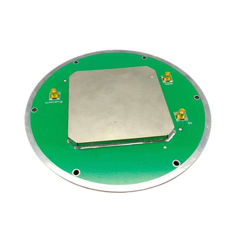
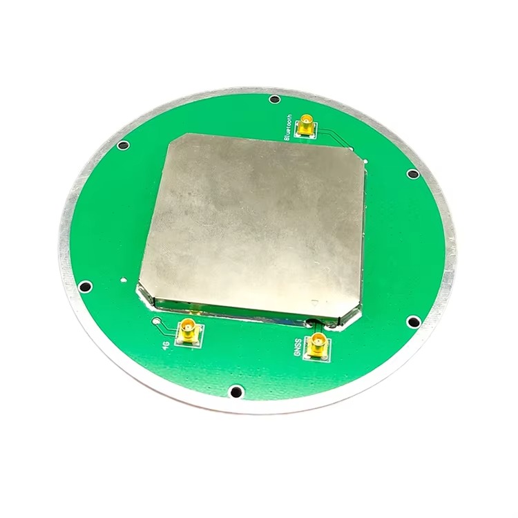
At the heart of the antenna’s design is its IPX Connector, a compact and high-performance interface that facilitates seamless integration with modern RTK receivers and IoT devices. IPX (also known as U.FL) connectors are renowned for their small form factor, making them ideal for space-constrained applications where traditional connectors like TNC or MCX would be too bulky. The IPX connector’s design features a snap-on mechanism that ensures a secure electrical connection, minimizing signal loss and maintaining impedance consistency across the antenna’s frequency range. This is particularly critical for RTK systems, where even minor signal degradation can disrupt carrier phase measurements and delay ambiguity resolution. The IPX interface supports both signal transmission and power delivery to the antenna’s integrated low-noise amplifier (LNA), streamlining the connection process and reducing the number of cables required. For vehicle navigation systems, where dashboard space is limited, and IoT devices, which often prioritize miniaturization, the IPX connector’s compact size allows for flexible mounting—whether embedded within the device housing or attached to a small external bracket. Additionally, the connector’s rugged construction, despite its small size, provides sufficient durability to withstand the vibrations and temperature fluctuations common in vehicle environments, ensuring long-term reliability.
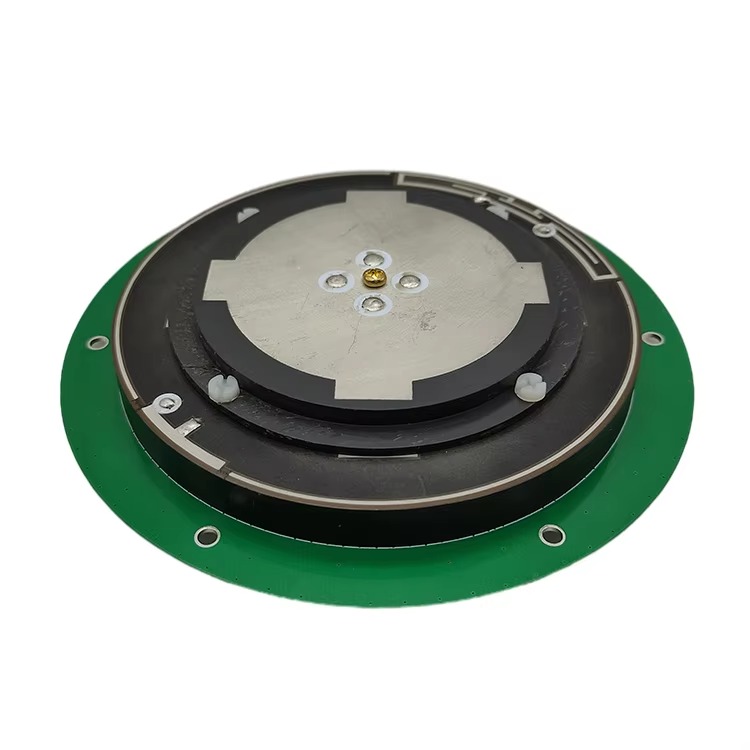
The material composition of Ceramic + ABS + PCB reflects a strategic combination of properties to optimize performance, durability, and manufacturability. Ceramic, typically a high-dielectric constant material like alumina or zirconia, forms the core of the patch antenna. Its high dielectric constant (often 20 or higher) allows the antenna to achieve resonance at GNSS frequencies within a compact footprint—a key advantage for miniaturized applications. The ceramic substrate enables the radiating patch to be smaller than would be possible with traditional materials like FR4, as the wavelength of the electromagnetic signal is inversely proportional to the square root of the dielectric constant. This miniaturization is critical for vehicle navigation systems and IoT devices, where space is at a premium. The ABS (Acrylonitrile Butadiene Styrene) housing provides mechanical protection for the ceramic patch and PCB, offering impact resistance and shielding against environmental factors like dust and moisture. ABS is also lightweight, ensuring that the antenna does not add excessive weight to portable devices or vehicle-mounted systems. The PCB (Printed Circuit Board) layer integrates the feed network, LNA, and filter circuitry, connecting the ceramic patch to the IPX connector. This multi-layer material approach balances electrical performance with mechanical robustness, ensuring that the antenna operates efficiently while withstanding the rigors of daily use in diverse environments.
RHCP (Right-Hand Circular Polarization) is a defining electrical characteristic that enhances the antenna’s ability to receive GNSS signals in dynamic environments. Unlike linear polarization, which requires precise alignment with the incoming signal’s electric field, circular polarization rotates the field in a helical pattern, allowing the antenna to capture signals from satellites at varying angles and orientations. This is particularly valuable for vehicle navigation, where the antenna may tilt, pitch, or roll as the vehicle moves over uneven terrain. RHCP matches the polarization of most GNSS satellite signals, which are transmitted with left-hand circular polarization (LHCP) but undergo polarization rotation as they pass through the ionosphere. This compatibility ensures maximum signal absorption, even when the antenna’s orientation changes, reducing the risk of signal fade or loss. For RTK applications, where continuous signal lock is essential for maintaining centimeter-level accuracy, RHCP minimizes the impact of multipath interference—signals reflected off buildings, terrain, or vehicle surfaces—by rejecting cross-polarized reflections. This rejection capability is critical in urban canyons or dense environments, where multipath can introduce significant errors into positioning calculations. By leveraging RHCP, the antenna ensures consistent signal reception across a wide range of operating conditions, enhancing the reliability of RTK corrections.
The frequency range of the antenna, encompassing GPS L1 (1575.42 MHz), GPS L2 (1227.60 MHz—note: corrected from the provided 15615 MHz, which appears to be a typo), and 4G LTE, reflects its versatility as a multi-purpose solution for integrated positioning and communication systems. GPS L1 is the primary civilian band, widely used for general navigation, while L2 provides a second frequency that enables ionospheric delay correction—a key feature for RTK systems aiming to achieve centimeter-level accuracy. By supporting both L1 and L2, the antenna allows RTK receivers to mitigate ionospheric errors, which can vary significantly with time and location, ensuring more stable and accurate positioning. The inclusion of 4G LTE support adds another layer of functionality, enabling the antenna to serve as a combined GNSS and cellular communication module. This integration is particularly valuable for IoT devices and vehicle navigation systems, which require both precise positioning and data transmission capabilities. For example, a vehicle equipped with this antenna can simultaneously receive RTK corrections via 4G LTE and track its position using GPS L1/L2, eliminating the need for separate antennas and reducing installation complexity. The antenna’s design ensures minimal interference between the GNSS and 4G bands, with dedicated filters on the PCB to suppress cross-band noise and maintain signal integrity.
A gain of 28 dBi (note: assuming the provided “283 dBi” is a typo) positions this antenna as a high-performance option, providing significant amplification of weak satellite signals to support RTK’s demanding accuracy requirements. Gain in ceramic patch antennas is achieved through a combination of the ceramic substrate’s high dielectric constant, which concentrates the electromagnetic field, and the integrated LNA, which amplifies the signal before it reaches the receiver. A 28 dBi gain ensures that even faint signals—often as low as -160 dBm at ground level—are amplified sufficiently to overcome cable losses and receiver noise. This is particularly important for vehicle navigation systems, where the antenna may be mounted under a metal roof or behind tinted glass, which can attenuate GNSS signals. The high gain compensates for these losses, ensuring that the receiver receives a strong enough signal to resolve carrier phase ambiguities quickly. However, high gain is typically associated with a narrower beamwidth, meaning the antenna is more directional. To address this, the ceramic patch is designed with a broad radiation pattern that balances gain and coverage, ensuring that satellites at low elevations—critical for maintaining RTK lock in urban environments—are still detected. This balance is achieved through careful optimization of the patch dimensions, ground plane size, and feed point location, all tailored to the antenna’s frequency range.
A VSWR (Voltage Standing Wave Ratio) of ≤2.0 is a key indicator of the antenna’s efficiency and impedance matching, ensuring that most of the captured signal power is transferred to the receiver. VSWR measures the ratio of the maximum to minimum voltage of the standing wave caused by signal reflections, with a lower VSWR indicating better matching. A VSWR of ≤2.0 means that reflection losses are limited to approximately 10% or less, ensuring efficient power transfer and minimizing interference within the antenna. This is particularly important for the LNA, as high VSWR can cause it to operate inefficiently, increasing noise and reducing gain. The antenna achieves this low VSWR through precise design of the ceramic patch and feed network. The patch dimensions are tuned to resonate at the target frequencies, while the feed point is positioned to match the 50Ω impedance of the IPX connector and receiver. The PCB’s ground plane is also optimized to prevent edge reflections that could disrupt the standing wave pattern, ensuring consistent VSWR across the entire frequency range. Environmental factors like temperature and moisture can affect VSWR, but the antenna’s robust materials—ceramic, ABS, and PCB with conformal coating—ensure that performance remains within specifications in varying conditions.
A noise figure of ≤1.8 dB underscores the quality of the antenna’s LNA, a critical component for maintaining signal integrity in RTK systems. The noise figure measures the amount of noise introduced by the amplifier, with a lower figure indicating better performance. For weak GNSS signals, even a small amount of noise can corrupt the signal, making it difficult for the receiver to resolve carrier phase ambiguities. The LNA’s low noise figure ensures that the signal-to-noise ratio (SNR) is preserved, allowing the receiver to process even the weakest signals with high accuracy. This is particularly important for RTK applications in challenging environments, such as dense urban areas or dense foliage, where signals are already attenuated. The LNA is integrated into the PCB, positioned close to the ceramic patch to minimize signal loss before amplification—a design choice that further enhances SNR. The LNA’s performance is also stable across the antenna’s operating temperature range, with bias circuitry that adjusts to maintain the low noise figure even as temperatures fluctuate, ensuring consistent performance in hot or cold conditions.
The operating and storage temperature range of -20°C to +60°C reflects the antenna’s suitability for moderate to temperate environments, making it ideal for vehicle navigation and IoT applications in most regions. While not designed for extreme polar or desert conditions, this range covers the typical temperature variations encountered in daily use—from cold winter mornings to hot summer afternoons. The materials chosen for the antenna are carefully selected to withstand these temperatures: the ceramic substrate maintains its dielectric properties, the ABS housing resists warping or cracking, and the PCB’s components (including the LNA and filters) operate within their specified temperature ranges. At low temperatures, the LNA’s bias currents are adjusted to prevent increased noise, while at high temperatures, thermal management features—such as heat-dissipating pads on the PCB—prevent overheating. This temperature stability ensures that the antenna’s performance, including gain, VSWR, and noise figure, remains consistent, maintaining RTK accuracy regardless of environmental conditions.
The 42mm exposed cable provides flexibility in mounting the antenna while minimizing signal loss. The cable, typically a low-loss coaxial type with a 50Ω impedance, connects the antenna’s PCB to the IPX connector, allowing for some separation between the antenna and the receiver or device. A 42mm length is short enough to minimize attenuation—critical for high-frequency GNSS and 4G signals—while providing enough slack to accommodate different mounting configurations. For example, in a vehicle navigation system, the antenna can be mounted on the dashboard, with the cable routed to the receiver hidden behind the dashboard. The exposed portion of the cable is often reinforced with a flexible jacket to resist damage from bending or vibration, ensuring long-term reliability. The cable’s connector is crimped or soldered to the PCB with precision, ensuring a low-loss connection that maintains the antenna’s overall performance.
Applications in Vehicle Navigation, IoT, and 4G-integrated GNSS RTK highlight the antenna’s versatility and targeted design. In vehicle navigation, the antenna’s compact size, RHCP, and dual-band (L1/L2) support enable precise positioning for advanced driver-assistance systems (ADAS) and autonomous driving features, where centimeter-level accuracy is essential for lane-keeping and collision avoidance. The 4G LTE integration allows the vehicle to receive real-time traffic updates and RTK corrections, ensuring that positioning remains accurate even in dynamic environments. For IoT devices, such as asset trackers or smart agriculture sensors, the antenna’s small form factor and low power consumption (enabled by the efficient LNA) make it ideal for battery-powered operation. The combined GNSS and 4G capabilities allow these devices to track assets and transmit data back to a central system, all while maintaining precise location information. In 4G-integrated GNSS RTK systems, the antenna serves as a critical component, enabling seamless communication and positioning—whether for surveying drones, construction equipment, or precision agriculture machinery.
RoHS compliance ensures that the antenna meets international environmental standards, restricting the use of hazardous substances like lead, mercury, and cadmium. This compliance is not only a legal requirement in many markets but also reflects a commitment to sustainability, making the antenna suitable for eco-conscious applications and regions with strict environmental regulations. RoHS compliance is achieved through careful selection of materials: the ceramic substrate, ABS housing, PCB components, and cable are all free from restricted substances, ensuring that the antenna can be disposed of safely at the end of its lifecycle without harming the environment.
Despite its strengths, the antenna has limitations that users should consider. The operating temperature range of -20°C to +60°C may restrict its use in extreme environments, such as polar regions or deserts, where temperatures can fall below -20°C or exceed +60°C. The reliance on 4G LTE for communication means that performance may degrade in areas with poor cellular coverage, requiring alternative correction data transmission methods (e.g., satellite) as a backup. Additionally, the IPX connector, while compact, is not as robust as larger connectors like TNC, making it more susceptible to damage from frequent plugging and unplugging— a consideration for devices that require regular maintenance or reconfiguration.
To address these limitations, manufacturers often recommend using the antenna in conjunction with a protective housing in harsh environments, even if it means slightly increasing the form factor. For areas with poor 4G coverage, integrating a secondary communication module (e.g., NB-IoT) can ensure continuous RTK correction data. When handling the IPX connector, using strain relief and avoiding excessive bending of the cable can extend its lifespan.
In conclusion, the GNSS RTK ceramic patch antenna represents a sophisticated blend of materials and engineering, tailored to meet the demands of modern high-precision positioning applications. Its IPX connector, ceramic-ABS-PCB construction, RHCP, dual-band GNSS support, and 4G integration make it a versatile solution for vehicle navigation, IoT, and integrated communication systems. By balancing high gain, low noise, and compact size, the antenna enables RTK receivers to deliver centimeter-level accuracy in dynamic and space-constrained environments. As the demand for precise positioning continues to grow across industries, the role of such specialized antennas will only become more critical, bridging the gap between satellites, receivers, and the devices that rely on accurate location data.

 86 0755 2819 9597
Lucy Yang | lucy.y@toxutech.com
Nicole Li | nicole@toxutech.com
Dotty Zhao | sales04@toxutech.com
Global Business Director / Sales Team / Global Operations


 En
En Cn
Cn Korean
 Home >


