

-
Products -PCBA Manufacturing RF Connectors RF Cable Assemblys Embedded Antennas External Antennas Positioning Chips and Modules
RF Connectors

RF Cable Assemblys
Embedded Antennas
External Antennas
Positioning Chips and Modules


 Language


Language


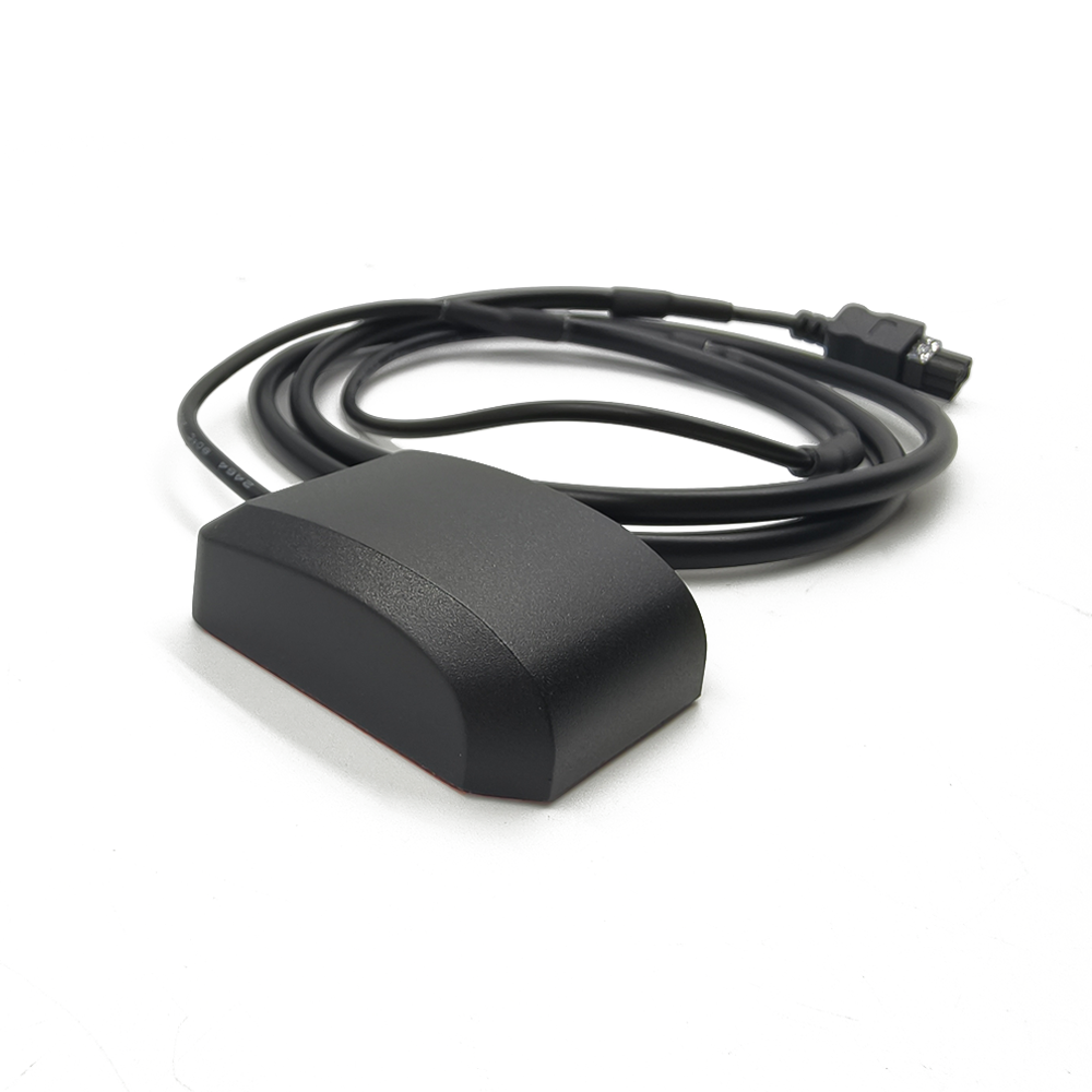

In the realm of Global Navigation Satellite Systems (GNSS), the external antenna serves as a critical bridge between the satellite constellations and the receiving device, playing a pivotal role in ensuring accurate, reliable, and consistent positioning data. This article delves into the intricate details of a specific GNSS external antenna, focusing on its key specifications—including connectivity, material, polarity, frequency range, impedance, VSWR, gain, voltage, size, and operating temperature—to unravel how each parameter contributes to its overall performance and suitability for various applications.
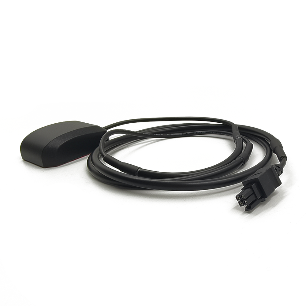
At the heart of any GNSS external antenna’s functionality lies its connectivity, as it dictates how effectively the antenna can transmit the received satellite signals to the host device. This particular antenna is equipped with a 4Pin Custom Connector, a design choice that carries significant implications for both performance and application flexibility. Unlike standard connectors, a custom 4-pin configuration is tailored to meet specific requirements, often balancing factors such as signal integrity, power delivery, and physical robustness.
The 4-pin design typically allocates pins for distinct purposes: two pins for signal transmission (one for the main signal and possibly a secondary or differential signal), one pin for power supply, and another for ground. This separation ensures that power interference does not corrupt the delicate GNSS signals, which are inherently weak due to their long travel distance from satellites (approximately 20,200 km for GPS satellites). By isolating the power and signal paths, the custom connector minimizes electromagnetic interference (EMI) and radio frequency interference (RFI), which can degrade signal quality and lead to positioning errors.
Custom connectors also offer advantages in terms of mechanical stability. They are engineered to fit precisely with the corresponding port on the target device, reducing the risk of accidental disconnection—a critical consideration in mobile applications such as automotive navigation, drones, or portable surveying equipment. Additionally, the custom nature allows for optimization of the connector’s size and weight, aligning with the antenna’s compact dimensions (49.53816.4mm) and ensuring compatibility with space-constrained environments.
It is worth noting that while custom connectors provide tailored benefits, they may introduce considerations regarding interoperability. Users must ensure that the antenna’s connector matches the device’s port, or that appropriate adapters are available. However, in many industrial and specialized applications, the performance gains from a custom-fit connector outweigh the potential drawbacks of reduced standardization.
Material: ABS
The choice of material for a GNSS external antenna is far from arbitrary; it directly impacts the antenna’s durability, signal transmission efficiency, and resistance to environmental factors. This antenna is constructed using Acrylonitrile Butadiene Styrene (ABS), a thermoplastic polymer renowned for its unique combination of mechanical strength, chemical resistance, and cost-effectiveness.
ABS is composed of three monomers: acrylonitrile, which contributes chemical and heat resistance; butadiene, which adds impact resistance and toughness; and styrene, which provides rigidity and a smooth, paintable surface. This blend results in a material that can withstand the rigors of outdoor and industrial environments, making it ideal for an external antenna that may be exposed to physical impacts, temperature fluctuations, and moisture.
One of the key advantages of ABS in antenna design is its electrical insulation properties. Unlike conductive materials, ABS does not interfere with the electromagnetic signals captured by the antenna’s internal elements (such as the radiating patch or dipole). This ensures that the signal path from the antenna’s receiver to the connector remains unobstructed, preserving signal integrity and maximizing the efficiency of signal transmission to the host device.
In terms of durability, ABS exhibits excellent impact resistance, even at low temperatures—a crucial feature given the antenna’s operating temperature range of -40°C to +85°C. This resilience prevents cracking or deformation in harsh conditions, such as those encountered in automotive applications (where the antenna may be mounted on the exterior of a vehicle) or in outdoor industrial settings (e.g., construction sites or agricultural machinery).
ABS is also resistant to a wide range of chemicals, including oils, greases, and many solvents, which further enhances its suitability for industrial environments. This resistance ensures that the antenna’s housing remains intact and functional even when exposed to common contaminants, reducing the need for frequent maintenance or replacement.
Additionally, ABS is relatively lightweight, which aligns with the antenna’s compact size (49.53816.4mm). The low weight of the material minimizes the load on mounting structures, making it easier to install the antenna in various locations without compromising stability. For example, in drone applications, where weight is a critical factor for flight performance, the use of ABS helps keep the overall system weight low while maintaining structural integrity.
The material’s moldability is another significant benefit. ABS can be easily injection-molded into complex shapes with tight tolerances, allowing for precise manufacturing of the antenna’s housing. This precision ensures that the internal components (such as the radiating element and circuit board) are held in optimal alignment, which is essential for maintaining the antenna’s electrical performance specifications, including gain and VSWR.
Polarity, in the context of antennas, refers to the orientation of the electric field of the transmitted or received electromagnetic wave. This GNSS external antenna features linear polarity, a design choice that is closely aligned with the characteristics of GNSS satellite signals and offers distinct advantages in terms of signal reception and application flexibility.
GNSS satellites, including those in the GPS, GLONASS, Galileo, and BeiDou constellations, transmit signals with linear polarization. Specifically, the L1 C/A Band (1575.42 MHz) signals— which this antenna is designed to receive—are linearly polarized. This alignment between the antenna’s polarity and the satellite signals ensures maximum signal coupling, as the antenna is optimized to capture electromagnetic waves with an electric field oriented in a specific linear direction (either vertical or horizontal, depending on the antenna’s design).
Linear polarization is particularly advantageous in scenarios where the antenna’s orientation relative to the satellites is relatively stable. For example, in fixed applications such as surveying equipment or stationary monitoring stations, the antenna can be mounted with a known orientation, ensuring that its linear polarization aligns with the incoming satellite signals. This alignment minimizes signal loss due to polarization mismatch, which can occur if the antenna’s polarity does not match that of the incoming wave.
In mobile applications, such as automotive or marine navigation, the antenna’s orientation may change dynamically as the vehicle moves. However, linear polarization remains effective in these scenarios because the satellite signals, while linearly polarized, arrive from multiple satellites in different positions in the sky. This diversity in signal paths means that even if the antenna’s orientation shifts, some signals will still be received with minimal polarization loss.
Compared to circular polarization—another common antenna polarity—linear polarization offers certain benefits. Linear polarized antennas are often simpler in design and more cost-effective to manufacture, making them a practical choice for many commercial and industrial applications. They also tend to exhibit higher gain in their intended polarization direction, which can enhance signal strength in environments where signal levels are marginal, such as urban canyons or dense foliage.
It is important to note that the performance of a linearly polarized antenna is dependent on proper installation. Misalignment with the dominant polarization of the incoming signals can lead to significant signal attenuation. However, in GNSS applications, where signals arrive from multiple directions with varying polarizations (due to reflections and scattering in the environment), the impact of minor misalignment is often mitigated. Additionally, many modern GNSS receivers are designed to work effectively with linearly polarized antennas, further ensuring reliable performance.
The frequency range of a GNSS antenna is a defining characteristic that determines which satellite signals it can receive, directly influencing its compatibility with different navigation systems and its performance in various environments. This antenna is specifically tuned to the L1 C/A Band, operating at 1575.42 MHz—a frequency that holds immense significance in global navigation.
The L1 band is one of the primary frequency bands used by GNSS constellations, including GPS (United States), GLONASS (Russia), Galileo (European Union), and BeiDou (China). The C/A (Coarse/Acquisition) code is a civilian signal transmitted on the L1 band, making it accessible to a wide range of consumer and industrial devices. This universality ensures that the antenna can be used with most standard GNSS receivers, providing compatibility with global navigation systems and enabling positioning accuracy suitable for applications such as automotive navigation, outdoor recreation, and asset tracking.
Operating at 1575.42 MHz offers several advantages. Firstly, the L1 C/A signal is relatively robust and easy to acquire, even in challenging environments. This is because the C/A code has a longer wavelength (approximately 19 cm) compared to higher-frequency GNSS signals (such as the L5 band), which allows it to penetrate obstacles such as foliage, light building materials, and inclement weather with less attenuation. This makes the L1 C/A Band antenna a reliable choice for applications where signal obstruction is common.
Secondly, the L1 band is widely supported by existing infrastructure and receiver technology. Most GNSS chipsets and modules are designed to process L1 C/A signals, ensuring that the antenna can be integrated seamlessly into a vast array of devices without the need for specialized hardware. This compatibility reduces development costs and time-to-market for manufacturers, making the antenna an attractive option for mass-produced consumer electronics and industrial equipment.
However, it is important to acknowledge the limitations of relying solely on the L1 C/A Band. The C/A code provides a moderate level of positioning accuracy (typically within 10-15 meters in open sky conditions), which may be insufficient for high-precision applications such as surveying, precision agriculture, or autonomous vehicles. These applications often require the use of additional frequency bands (such as L2 or L5) and advanced techniques like Real-Time Kinematic (RTK) positioning. Nevertheless, for many mainstream applications, the accuracy provided by the L1 C/A Band is more than adequate.
Another consideration is the potential for interference in the L1 band. As a widely used frequency, it may be susceptible to intentional or unintentional jamming, which can disrupt signal reception. However, modern GNSS antennas, including this model, are often designed with built-in filtering and interference mitigation features to minimize the impact of such disruptions. Additionally, the antenna’s gain of 28 dBi (discussed in detail later) helps to amplify the weak incoming signals, improving reception even in the presence of moderate interference.
Impedance is a fundamental electrical property that describes the opposition a circuit presents to the flow of alternating current (AC) at a given frequency. For GNSS antennas, maintaining a consistent impedance is critical for ensuring efficient signal transfer between the antenna and the connected receiver. This antenna is designed with an impedance of 50 Ohms—a standard value in RF (radio frequency) engineering that plays a vital role in optimizing performance.
The 50 Ohm impedance standard has become ubiquitous in RF systems, including GNSS, due to a balance between power handling and signal loss. In antenna design, impedance matching between the antenna and the transmission line (cable) connecting it to the receiver is essential to minimize signal reflection. When the impedance of the antenna matches that of the transmission line and the receiver, the maximum amount of signal power is transferred, with minimal loss due to reflection.
Reflections can significantly degrade antenna performance. When a signal encounters an impedance mismatch, a portion of the power is reflected back toward the antenna, rather than being absorbed by the receiver. This reflected power can cause standing waves along the transmission line, leading to increased signal loss, reduced sensitivity, and even potential damage to the receiver’s front-end components in extreme cases. By designing the antenna with a 50 Ohm impedance, manufacturers ensure compatibility with the vast majority of RF cables and receivers, which are also standardized to 50 Ohms, thus minimizing reflections and maximizing power transfer.
The 50 Ohm impedance also aligns with the electrical characteristics of the L1 C/A Band (1575.42 MHz). Antenna impedance is not a constant value across all frequencies; it varies with frequency due to the antenna’s physical dimensions and resonant properties. The antenna is specifically tuned to exhibit 50 Ohms at 1575.42 MHz, ensuring optimal performance at its intended operating frequency. This tuning is achieved through careful design of the radiating element, ground plane, and any matching networks incorporated into the antenna’s structure.
In practical terms, the 50 Ohm impedance simplifies system integration. Engineers and users can confidently connect the antenna to standard RF components without the need for complex impedance-matching circuits, reducing design complexity and cost. This is particularly important in mass-market applications, where ease of integration and cost-effectiveness are key considerations.
VSWR: ≤2.0
Voltage Standing Wave Ratio (VSWR) is a critical parameter that quantifies the efficiency of power transfer between the antenna and the transmission line/receiver. This antenna specifies a VSWR of ≤2.0, a value that indicates a high level of impedance matching and efficient signal transmission.
VSWR is defined as the ratio of the maximum voltage to the minimum voltage of the standing wave formed along the transmission line due to signal reflections. A VSWR of 1.0 (or 1:1) represents a perfect match, where there are no reflections, and all signal power is transferred to the receiver. As the VSWR increases, the amount of reflected power increases, and the efficiency of power transfer decreases. A VSWR of 2.0 means that the reflected power is no more than 11% of the incident power, with 89% of the power being transferred to the receiver—an acceptable level for most GNSS applications.
The VSWR specification of ≤2.0 is particularly significant for this antenna, as it ensures that even in real-world operating conditions (where factors such as temperature, humidity, and physical orientation can slightly alter the antenna’s impedance), the impedance mismatch remains minimal. This stability is crucial for maintaining consistent performance, especially in dynamic environments such as moving vehicles or drones, where the antenna’s orientation and surrounding conditions can change rapidly.
A low VSWR is directly linked to the antenna’s ability to maintain signal integrity. High VSWR can lead to increased noise in the received signal, reduced sensitivity, and degraded positioning accuracy. By limiting VSWR to ≤2.0, the antenna ensures that the signal-to-noise ratio (SNR) remains high, allowing the receiver to accurately decode the GNSS signals and compute precise position fixes.
The antenna’s design—including its 50 Ohm impedance, careful tuning to the L1 C/A Band, and use of quality materials—contributes to achieving this low VSWR. The custom 4-pin connector also plays a role, as a secure and precise connection minimizes additional impedance mismatches at the interface between the antenna and the transmission line.
In practical applications, a VSWR of ≤2.0 is more than sufficient for most consumer and industrial GNSS use cases. For example, in automotive navigation, where the antenna is mounted on the roof or windshield, a low VSWR ensures that even with minor vibrations or temperature changes, the signal reception remains reliable. In portable devices, such as handheld GPS units, the low VSWR helps to maximize battery life by minimizing power loss, as less energy is wasted on reflected signals.
It is important to note that VSWR can be affected by external factors, such as the antenna’s mounting location and nearby objects. Metal structures, for example, can alter the antenna’s impedance and increase VSWR. However, the antenna’s design is optimized to minimize such effects, ensuring that the VSWR remains within the specified limit under typical operating conditions.
Gain: 28 dBi
Gain is a key performance metric that measures an antenna’s ability to focus or amplify incoming signals in a specific direction compared to a reference antenna (typically an isotropic antenna, which radiates equally in all directions). This GNSS external antenna boasts a gain of 28 dBi—a relatively high value that significantly enhances its ability to receive weak satellite signals and improve positioning accuracy.
The term “dBi” (decibels relative to an isotropic antenna) quantifies the antenna’s gain in a given direction. A gain of 28 dBi indicates that the antenna is highly directional, focusing its reception (and transmission, although GNSS antennas are primarily receive-only) in a specific area—typically the sky, where GNSS satellites are located. This directional focus allows the antenna to capture more signal power from satellites while reducing interference from signals coming from other directions (such as ground-based noise sources).
High gain is particularly beneficial in challenging environments where satellite signals are weak or attenuated. For example, in urban canyons—areas with tall buildings—signals from low-elevation satellites may be blocked or reflected, leading to multipath interference (where the receiver receives multiple versions of the same signal, each reflected off different surfaces). A high-gain antenna can better capture signals from high-elevation satellites, which are less likely to be blocked by buildings, improving positioning accuracy and reliability.
Similarly, in dense foliage or under tree canopies, satellite signals are attenuated by leaves and branches. The 28 dBi gain helps to amplify the remaining weak signals, ensuring that the receiver can still acquire and track the satellites. This makes the antenna suitable for outdoor recreational activities such as hiking, camping, and hunting, as well as for agricultural applications where equipment may operate in rural areas with significant vegetation.
The high gain of this antenna is achieved through its design, which likely incorporates a directional radiating element (such as a patch antenna or a helical antenna) and a ground plane to focus the signal reception toward the sky. The use of ABS material also contributes, as its low dielectric loss ensures that the signal captured by the radiating element is not significantly absorbed or attenuated as it travels to the connector.
It is important to note that high gain is accompanied by a narrower beamwidth. A directional antenna with high gain focuses on a smaller area of the sky, meaning that it may need to be properly aligned (e.g., mounted with a clear view of the sky) to maximize performance. However, this is a trade-off that is well worth it for applications requiring reliable reception in challenging conditions. Modern GNSS receivers also work in conjunction with high-gain antennas by tracking multiple satellites simultaneously, ensuring that even with a narrower beamwidth, sufficient satellites are visible to compute a position fix.
Voltage: 3.3V 5V
The operating voltage of a GNSS antenna is a critical parameter that determines the power requirements for its internal electronics, such as low-noise amplifiers (LNAs) used to boost weak incoming signals. This antenna operates within a voltage range of 3.3V to 5V—a range that offers significant flexibility for integration into a wide variety of devices and systems. This voltage range is carefully chosen to align with the power requirements of the antenna’s internal components while ensuring compatibility with common power sources in both consumer and industrial electronics.
The LNA is a critical component in any GNSS antenna, as it amplifies the weak signals received from satellites (which can be as low as -160 dBm) before they are transmitted to the receiver. This amplification is essential to overcome the noise introduced by the transmission line and the receiver’s front-end circuitry, ensuring that the signal remains detectable and decodable. The LNA requires a stable power supply to operate efficiently, and the 3.3V to 5V range is well-suited to meet this need.
One of the primary advantages of this voltage range is its compatibility with standard power sources. Many electronic devices, including microcontrollers, single-board computers, and GNSS receiver modules, operate on either 3.3V or 5V. This means that the antenna can be powered directly from the host device without the need for additional voltage regulation circuitry, simplifying system design and reducing costs. For example, in a drone navigation system, the antenna can draw power from the drone’s main battery through a 5V regulator, while in a handheld GPS unit, it can be powered by the device’s 3.3V internal power supply.
The ability to operate at both 3.3V and 5V also provides redundancy and flexibility in power management. In systems where power supply voltage may fluctuate slightly (such as battery-powered devices), the antenna’s ability to function reliably across this range ensures consistent performance. For instance, as a battery discharges, its voltage may drop from 5V to 3.3V, but the antenna will continue to operate without degradation, ensuring uninterrupted navigation data.
It is important to note that the antenna’s power consumption is optimized for this voltage range. While the exact current draw depends on the specific design of the LNA and other components, it is typically low enough to be compatible with battery-powered devices, extending their operational life. This is particularly important in applications such as portable surveying equipment or outdoor tracking devices, where long battery life is a key requirement.
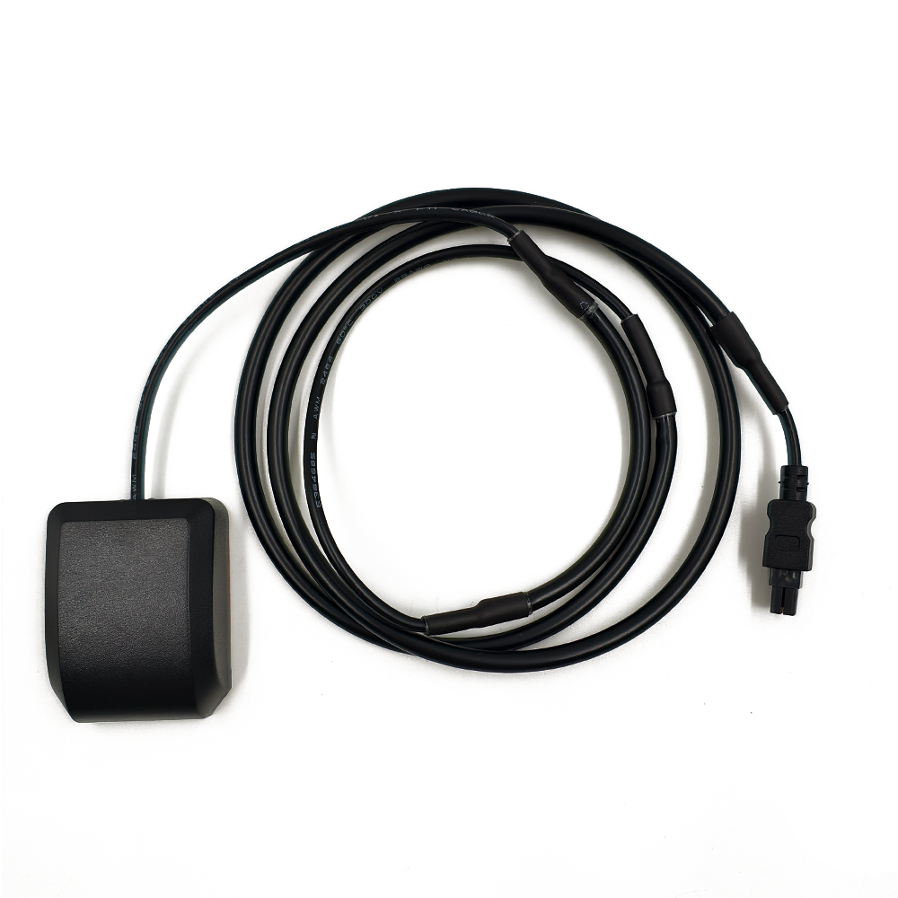
Antenna Size: 49.53816.4mm
The physical dimensions of a GNSS external antenna play a crucial role in determining its suitability for various applications, influencing factors such as mounting flexibility, aerodynamics, and integration into space-constrained devices. This antenna features compact dimensions of 49.5mm x 38mm x 16.4mm—a design that balances performance with versatility, making it ideal for a wide range of use cases.
The small size of the antenna is a significant advantage in applications where space is limited. For example, in automotive installations, the antenna can be mounted in discrete locations such as the windshield, roof pillar, or rearview mirror housing without obstructing the driver’s view or detracting from the vehicle’s aesthetics. Similarly, in drone design, where weight and aerodynamics are critical, the compact size minimizes air resistance and allows for easier integration into the drone’s frame without compromising flight performance.
The antenna’s low profile (16.4mm in height) is particularly beneficial for applications where a sleek, unobtrusive design is desired. In marine navigation systems, for instance, the antenna can be mounted on the boat’s dashboard or console without taking up excessive space, ensuring that other equipment remains accessible. In portable devices such as handheld GPS units or fitness trackers, the small size allows for a lightweight and ergonomic design, enhancing user comfort during extended use.
Despite its compact dimensions, the antenna is engineered to maintain high performance. The radiating element and internal components are carefully designed to fit within the small housing while still achieving the specified gain (28 dBi), frequency range (L1 C/A Band), and VSWR (≤2.0). This is made possible through advanced manufacturing techniques and materials, such as the use of ABS for the housing, which allows for precise molding of internal structures to optimize signal propagation.
The size of the antenna also impacts its durability and ruggedness. A smaller housing is inherently more resistant to physical damage, as there is less surface area exposed to impacts. This, combined with the use of ABS material, makes the antenna well-suited for harsh environments, such as construction sites or off-road vehicles, where it may be exposed to vibrations, dust, and debris.
In terms of transportation and storage, the compact size of the antenna is a practical benefit. It can be easily packaged and shipped, reducing logistics costs, and takes up minimal space in storage, making it convenient for inventory management. This is particularly important for manufacturers and distributors dealing with large quantities of antennas.
Operating Temp: -40°C to +85°C
The operating temperature range of a GNSS external antenna is a critical specification that determines its reliability and performance in extreme environmental conditions. This antenna is designed to operate within a temperature range of -40°C to +85°C—a wide range that ensures it can function effectively in some of the most challenging climates and environments on Earth.
At the lower end of the range, -40°C is a temperature encountered in polar regions, high-altitude environments, and during severe winter conditions in temperate zones. The antenna’s ability to operate at this temperature is largely due to the use of ABS material for the housing, which retains its impact resistance and structural integrity even in extreme cold. Additionally, the internal electronics, such as the LNA, are designed with components that can withstand low temperatures without experiencing performance degradation. This ensures that the antenna continues to amplify weak satellite signals and transmit them to the receiver, even in freezing conditions—a crucial feature for applications such as Arctic expeditions, high-altitude balloon missions, or winter sports tracking.
At the upper end of the range, +85°C is a temperature found in desert regions, inside enclosed vehicles exposed to direct sunlight, and in industrial environments such as factories or power plants. The antenna’s ability to withstand high temperatures is again attributed to the properties of ABS, which has a relatively high melting point and retains its mechanical strength at elevated temperatures. The internal electronics are also designed with thermal management in mind, using components rated for high-temperature operation and ensuring that heat is dissipated effectively to prevent overheating. This ensures reliable performance in hot climates, such as desert navigation or construction sites in tropical regions, where temperatures can soar during the day.
The wide operating temperature range also ensures that the antenna remains stable during rapid temperature fluctuations. For example, in automotive applications, the antenna may be exposed to extreme cold overnight, followed by rapid heating as the sun rises. The antenna’s components must be able to expand and contract with temperature changes without losing functionality or structural integrity. The use of high-quality materials and precise manufacturing techniques ensures that the antenna can handle these fluctuations without degradation.
In addition to temperature extremes, the antenna’s operating range also implies resistance to condensation and moisture. At low temperatures, moisture in the air can condense on the antenna’s surface or inside its housing, potentially causing electrical shorts or corrosion. The antenna’s design likely includes seals or coatings to prevent moisture ingress, ensuring that it remains functional even in humid or wet conditions. This is particularly important for marine applications or outdoor equipment used in rainy environments.
The GNSS external antenna described in this article is a highly engineered device that combines a range of specifications to deliver reliable and accurate positioning performance. From its 4Pin Custom Connector, which ensures optimal signal integrity and mechanical stability, to its ABS housing, which provides durability and electrical insulation, each component is designed to contribute to the antenna’s overall functionality.
The antenna’s linear polarity aligns with the characteristics of GNSS satellite signals, while its tuning to the L1 C/A Band ensures compatibility with global navigation systems. The 50 Ohm impedance and VSWR of ≤2.0 minimize signal reflections and maximize power transfer, while the high gain of 28 dBi enhances signal reception in challenging environments.
The 3.3V to 5V voltage range offers flexibility in power management, and the compact size of 49.53816.4mm allows for easy integration into a wide range of devices and applications. Finally, the operating temperature range of -40°C to +85°C ensures that the antenna can perform reliably in extreme environmental conditions.
Together, these specifications make this GNSS external antenna a versatile and high-performance solution for a variety of applications, including automotive navigation, drones, portable surveying equipment, marine navigation, and outdoor recreation. Whether operating in urban canyons, dense foliage, extreme temperatures, or space-constrained environments, this antenna is designed to provide consistent and accurate positioning data, making it an essential component in modern navigation systems.

 86 0755 2819 9597
Lucy Yang | lucy.y@toxutech.com
Nicole Li | nicole@toxutech.com
Dotty Zhao | sales04@toxutech.com
Global Business Director / Sales Team / Global Operations


 En
En Cn
Cn Korean
 Home >


