Combo Antenna Combo Antenna

Language
Built-in RTK GPS Antenna
GNSS Car Antenna
GNSS Car Antenna

GPS & GNSS Antenna

Home >  GPS & GNSS Antenna > 

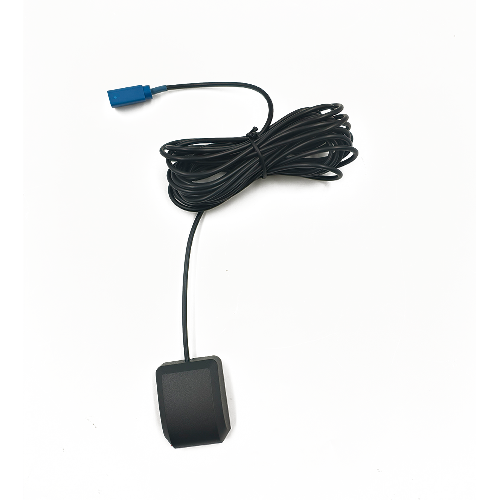
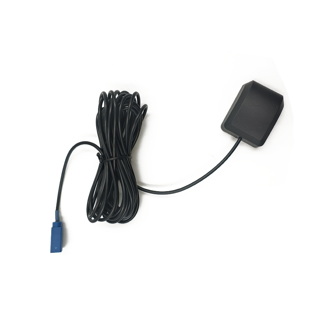
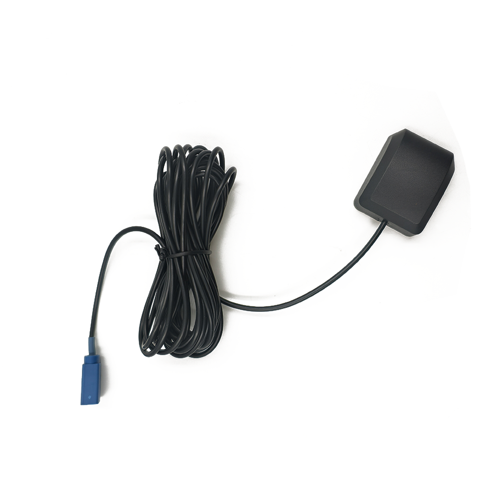
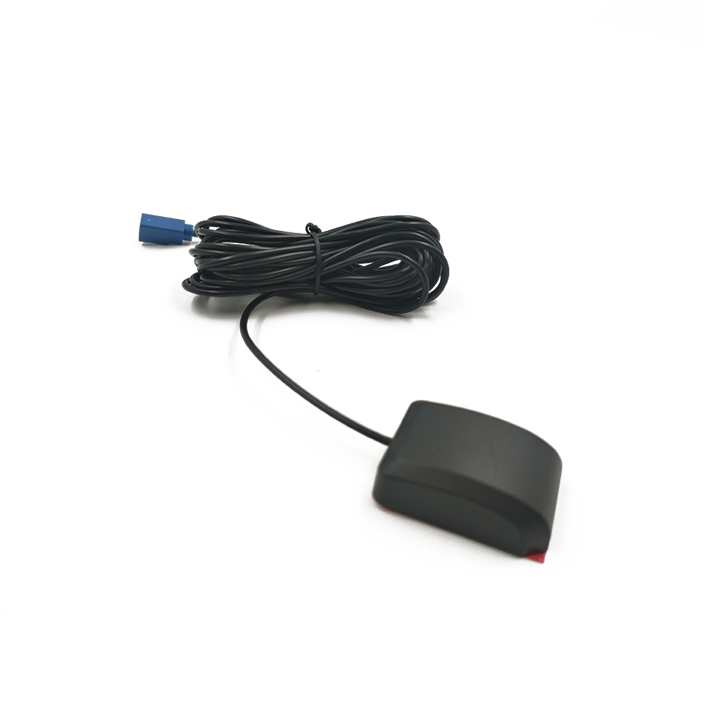
Fleet Management GNSS Antenna for telematics devices

In the modern era of logistics, supply chain management, and transportation, the concept of "knowing where your assets are" has evolved from a competitive advantage to an absolute operational necessity. At the heart of this capability lies the Global Navigation Satellite System (GNSS), and more specifically, the often-overlooked yet critically important component: the GNSS antenna. For fleet management telematics devices, the antenna is not just a piece of hardware; it is the primary gateway through which all location intelligence is acquired. It is the sensory organ that listens to the whispers from space, enabling the transformation of raw satellite signals into actionable data that drives efficiency, safety, and profitability.


Leave a message Contact

Fill in your email address

Or you can continue to download without filling in

Overview

A fleet management GNSS antenna is a specialized passive or active transducer designed to receive the very weak, right-hand circularly polarized (RHCP) microwave signals transmitted by constellations of navigation satellites orbiting the Earth. These constellations include the American GPS (Global Positioning System), the Russian GLONASS, the European Galileo, the Chinese BeiDou, and other regional augmentation systems. The primary function of the antenna is to capture these faint signals and convert them into electrical currents that can be amplified and processed by the connected telematics device's GNSS receiver.

The telematics ecosystem is a complex integration of hardware and software. While the telematics device itself (the "black box") contains the receiver, processor, cellular modem, and various input/output interfaces, the GNSS antenna is its direct link to the satellite constellations. Without a high-performance antenna, even the most advanced and sensitive receiver cannot function effectively. The antenna's performance directly dictates the quality, accuracy, and reliability of the location data, which forms the foundational layer for all subsequent telematics functions.

These functions are vast and integral to modern fleet operations:

    Real-Time Asset Tracking: Providing live visibility of vehicle location on a digital map.

    Route Optimization and Geofencing: Analyzing routes for efficiency and creating virtual geographical boundaries for alerts.

    Driver Behavior Monitoring: Tracking harsh events like acceleration, braking, and cornering, which are often correlated with location.

    Fuel Management: Monitoring idling times and route efficiency to reduce fuel consumption.

    Regulatory Compliance: Supporting the recording of Hours of Service (HOS) through Electronic Logging Devices (ELDs) which mandate precise location and movement data.

    Theft Recovery: Providing continuous location pings to aid in recovering stolen vehicles and cargo.

The environment in which these antennas operate is exceptionally challenging. They are mounted on vehicles that traverse diverse and signal-hostile terrains: dense urban canyons with severe multipath interference, open highways, tree-covered rural roads, and industrial areas with high electromagnetic interference. Furthermore, they must withstand extreme environmental conditionsfrom scorching heat and UV radiation to freezing temperatures, rain, ice, salt spray, and constant vibration.

Therefore, the overview of a fleet management GNSS antenna reveals it as a sophisticated, purpose-built component. It is the critical first node in a data chain that empowers managers to make informed decisions, reduce operational costs, enhance safety, and improve customer service. Its design is a constant battle against physics to extract a usable signal from a noisy environment, making it far more than a simple "GPS antenna" but a core enabler of intelligent transportation systems.


Design and Construction

The design and construction of a fleet management GNSS antenna are a meticulous exercise in electromagnetic engineering, materials science, and mechanical robustness. Every aspect, from the shape of the radiating element to the composition of the external radome, is optimized for one goal: to provide a stable, strong, and clean signal to the telematics receiver in the harshest of conditions. The architecture can be broken down into several key components and design philosophies.

1. The Radiating Element: The Heart of the Antenna

The most critical internal component is the radiating element, which is responsible for the actual reception of the satellite signals. For GNSS applications, patch antennas are overwhelmingly the design of choice due to their low profile, ruggedness, and predictable radiation pattern.

    Structure: Typically, it consists of a metallic patch (often copper) etched onto a dielectric substrate material. This patch is positioned over a ground plane, which helps to direct the antenna's reception pattern skyward. The size of the patch is precisely calculated based on the wavelength of the target GNSS frequencies (e.g., L1 band at 1575.42 MHz for GPS).

    Feed Point: The method of delivering the captured signal to the output cable is crucial. Designs often use probe feeding or aperture-coupled feeding to minimize losses and impedance mismatches.

    Multiband Support: Modern fleet antennas are rarely single-band (GPS L1 only). To leverage multiple constellations (GPS, GLONASS, Galileo, BeiDou) and augmentation systems (SBAS), the patch must be designed to resonate efficiently across multiple frequencies (e.g., L1, L2, L5 bands). This is achieved through sophisticated techniques like using multiple patches, slots within a single patch, or stacked patches.

2. The Ground Plane: Directing the Pattern

The ground plane is a conductive layer beneath the radiating patch. Its size and integrity are paramount. A larger ground plane helps to create a more hemispherical reception pattern, maximizing the view of the sky and reducing the antenna's sensitivity to signals arriving from low elevations (which are often reflected multipath signals). In fleet applications, where the antenna might be mounted on a metal vehicle roof (which acts as an ideal ground plane) or on a non-metallic surface, the antenna's built-in ground plane must be designed to compensate. Some antennas include a proprietary "ground plane technology" using radial patterns or other methods to mimic a large ground plane even when mounted on fiberglass or plastic.

3. The Amplifier (LNA - Low Noise Amplifier): Boosting the Faint Signal

GNSS signals are incredibly weak by the time they travel over 20,000 km to the Earth's surfaceoften compared to the light from a bright streetlamp viewed from across the continent. To make these signals usable, all active GNSS antennas incorporate a Low Noise Amplifier (LNA) located as close to the radiating element as possible.

    Function: The LNA's primary job is to amplify the signal while adding the absolute minimum amount of electronic noise itself (measured as Noise Figure). A good LNA has a high gain (e.g., 25-30 dB) and a very low noise figure (e.g., <1.5 dB).

    Placement: Positioning the LNA immediately after the radiating element helps to boost the signal before it incurs losses in the coaxial cable that connects to the telematics device. This is vital, as signal loss in a long cable can be significant, and amplifying after that loss would also amplify the noise.

    Filtering: The amplifier stage often includes built-in band-pass filters. These filters are tuned to the specific GNSS frequencies and are essential for rejecting out-of-band interference from powerful nearby sources like cellular transmitters (4G/5G), FM radio towers, and mobile two-way radios, which can easily overload a sensitive GNSS receiver.

4. The Radome: The Protective Shell

The radome is the external housing that protects the delicate internal components from the physical and environmental elements.

    Material: It is typically made from high-grade, weather-resistant plastic like polycarbonate or ABS. The material must be rigorously tested for UV stability to prevent yellowing and brittleness over years of sun exposure.

    Dielectric Properties: Crucially, the material must be radio frequency (RF) transparent. This means it must allow microwave signals to pass through with minimal reflection, absorption, or distortion. The thickness and composition are carefully chosen to avoid detuning the antenna.

    Design: The shape is often low-profile and aerodynamic to reduce wind noise and prevent accumulation of snow, ice, or water. A well-designed radome will also feature watertight seals (often using IP67 or IP69K standards) to prevent moisture ingress, which would severely degrade performance and lead to failure.

5. The Cable and Connector: The Signal Highway

The coaxial cable and connector form the critical link between the antenna and the telematics device.

    Cable Quality: High-quality, low-loss coaxial cable (e.g., RG-174, RG-58) is mandatory. Longer cables introduce more signal attenuation (loss), so the cable length is a trade-off between installation flexibility and signal strength.

    Shielding: The cable must have excellent shielding to prevent external electromagnetic interference (EMI) from vehicle electronics (e.g., alternator whine, engine control units) from corrupting the weak GNSS signal on its journey to the receiver.

    Connector: The connector, typically an SMA or FAKRA type, must provide a secure, weatherproof (if external), and reliable connection. A loose or corroded connector is a common source of GNSS failure in vehicles.

In summary, the construction of a fleet GNSS antenna is a holistic integration of these components. It balances electromagnetic performance with brutal mechanical and environmental durability. The choice of materials, the precision of the patch design, the quality of the LNA, and the resilience of the radome and cable all coalesce to determine whether the antenna will be a reliable ear to the skies or a fragile point of failure.


Working Principles

The operation of a fleet management GNSS antenna and its associated system is a fascinating process that involves advanced physics, signal processing, and geometry. The antenna's role, while only the first step, is fundamentally enabling. Its working principle is to act as a transducer and initial signal conditioner for the microwave signals emanating from the satellite constellations.

Step 1: Signal Reception and Transduction

Navigation satellites continuously broadcast microwave signals on specific frequencies. These signals are modulated with a pseudorandom code that identifies the satellite and contains data about its precise location and the exact time the signal was transmitted (using highly accurate atomic clocks onboard).

The GNSS antenna's radiating element (the patch) is designed to be particularly sensitive to these frequencies and their specific polarization (Right-Hand Circular Polarization - RHCP). RHCP is used because it is less susceptible to certain types of signal degradation caused by the atmosphere and reflections than linear polarization. As the electromagnetic waves from the satellites impinge upon the metal patch, they induce a tiny, oscillating electrical current within it. This is the process of transductionconverting energy from an electromagnetic wave into an electrical signal.

Step 2: Initial Amplification and Filtering

The electrical signal generated at the patch is extraordinarily weak, measured in microvolts or even nanovolts. It is also buried in a sea of natural and man-made radio noise. This is where the integrated Low Noise Amplifier (LNA) performs its critical function. It takes this miniscule signal and amplifies it significantly (by a factor of 25-30 dB). Crucially, it does this while adding as little additional electronic noise as possible. Simultaneously, integrated band-pass filters immediately reject strong, out-of-band signals from non-GNSS sources (e.g., cellular networks, radio broadcasts). This prevents these powerful signals from overloading the amplifier and the downstream receiver, ensuring that only the relevant GNSS frequency bands are amplified and passed on.

Step 3: Signal Transmission to the Receiver

The now-amplified and filtered signal is sent through the coaxial cable to the telematics device's GNSS receiver module. The use of a low-loss cable is vital here, as any attenuation in the cable would undo the work of the LNA. The receiver's front-end further processes the signal, but the antenna and LNA have already provided it with a clean, strong signal to work witha signal that is well above the noise floor of the receiver itself.

Step 4: Position Calculation (Receiver Function)

While the antenna's job is complete once it delivers the signal, understanding what the receiver does next highlights the importance of the antenna's quality. The receiver performs a complex series of operations:

    Acquisition and Tracking: It searches for the pseudorandom codes from different satellites and "locks onto" them. A high-quality signal from the antenna allows for faster "Time to First Fix" (TTFF)especially a cold startand more stable tracking.

    Data Decoding: It decodes the navigation message from each satellite, which contains information about the satellite's orbit (ephemeris data), health, and the precise time.

    Ranging: The core principle of GNSS is trilateration. The receiver calculates its distance to each satellite by measuring the time delay between the transmission of the code from the satellite and its reception. This requires incredibly precise timing, as light travels approximately 30 cm per nanosecond. The formula is: Distance = Speed of Light × Transmission Time.

    Position Solution: To determine a unique 3D position (latitude, longitude, altitude), the receiver needs signals from at least four satellites. With more satellites (often 10-20 with multi-constellation support), the solution becomes more robust and accurate. The receiver solves a system of equations based on the measured distances to each satellite, whose positions are known from the decoded ephemeris data.

The Critical Impact of Antenna Performance:

    Multipath Mitigation: A primary source of error in GNSS is multipath, where the signal reflects off buildings, the ground, or the vehicle itself before reaching the antenna. A well-designed antenna with a good ground plane and a sharp right-hand circularly polarized pattern is naturally resistant to these reflected signals (which often become elliptically or left-hand polarized), rejecting them and providing a cleaner, more direct signal to the receiver.

    Low-Noise Elevation Reception: The antenna's radiation pattern is designed to be most sensitive to signals from above the horizon and less sensitive to those near the horizon. This helps it prioritize signals from satellites directly overhead, which suffer less from atmospheric delay, while attenuating noisier, lower-elevation signals that are more prone to multipath and atmospheric errors.

In essence, the working principle of the GNSS antenna is to be a selective, sensitive, and low-noise collector of extremely faint signals from space. It conditions these signals to survive the journey to the receiver, which then performs the mathematical magic of turning time delays into a precise location on Earth. The fidelity of the initial signal capture directly dictates the accuracy, reliability, and speed of the entire positioning engine.


Advantages and Challenges

The deployment of a high-quality GNSS antenna within a fleet management system brings immense advantages, but it also must be designed to overcome a persistent set of physical and environmental challenges. Understanding this balance is key to selecting and deploying the right antenna solution.

Advantages of a Dedicated, High-Performance GNSS Antenna:

    Enhanced Accuracy and Precision: The primary advantage is superior positional accuracy. A well-designed antenna provides a stronger signal-to-noise ratio (SNR), better multipath rejection, and more stable phase center characteristics. This translates to fewer positioning "jumps" and more reliable data for geofencing, lane-level tracking, and event triggering (like harsh braking detection).

    Improved Reliability and Availability: By supporting multiple GNSS constellations (GPS, GLONASS, Galileo, BeiDou), a modern antenna dramatically increases the number of satellites visible to the receiver at any given time. This is crucial in "urban canyon" environments where the view of the sky is obstructed. With more satellites in view, the receiver has a higher probability of maintaining a position fix where a single-constellation system might fail completely.

    Faster Time to First Fix (TTFF): The combination of a sensitive antenna and a low-noise amplifier provides the receiver with a strong signal from the moment it's powered on. This allows it to acquire satellite signals and calculate a position much more quickly, especially important for cold starts or after long periods in a signal-denied environment (like a warehouse).

    Resistance to Interference and Jamming: Integrated filtering in the antenna's LNA stage provides the first line of defense against out-of-band interference from communications equipment on the vehicle itself (e.g., cellular modems, Wi-Fi, two-way radios) or in the environment. This prevents receiver desensitization and loss of lock.

    Robustness and Long-Term Durability: Purpose-built fleet antennas are engineered to withstand the harsh automotive environmentvibration, temperature extremes, UV radiation, moisture, and chemical exposure. This leads to a longer service life and lower total cost of ownership by reducing failures and maintenance needs compared to using consumer-grade antennas.

    Optimal Placement Flexibility: A dedicated external antenna can be mounted in an ideal location for signal reception, typically the center of the vehicle roof, which provides a full 360-degree view of the sky and utilizes the metal roof as a perfect ground plane. This is far superior to embedded antennas in telematics devices that may be mounted under the dashboard or in the trunk, surrounded by obstructions.

Challenges and Limitations:

    Multipath Propagation: This remains the single greatest challenge for urban fleet operations. Signals bouncing off buildings and other structures create erroneous path length calculations. While antenna design (ground plane, RHCP) mitigates this, it cannot eliminate it entirely, especially in deep urban canyons where no direct line-of-sight signals are available.

    Signal Blockage and Attenuation: Physical obstructions are a fundamental limitation. Dense tree cover, tunnels, underground parking garages, and even large loads on a truck can completely block GNSS signals. The antenna is powerless in these scenarios, leading to temporary data dropouts. This is often supplemented with dead reckoning systems using inertial sensors.

    Electromagnetic Interference (EMI): The modern vehicle is a noisy RF environment. While antennas have filters, extremely strong or close-range interference from intentional jammers, faulty vehicle electronics, or high-power transmitters can still overwhelm the system and cause a loss of signal.

    Intentional Jamming and Spoofing: The widespread availability of low-cost GNSS jammers poses a significant threat. These devices transmit noise on the GNSS frequencies, drowning out the legitimate satellite signals and causing the receiver to lose lock. More sophisticated spoofing devices broadcast false but legitimate-looking GNSS signals, tricking the receiver into reporting an incorrect location. Antennas alone cannot defeat this; advanced receiver-level cryptographic authentication techniques are required.

    Installation and Maintenance Challenges: The performance is highly dependent on correct installation. A poorly mounted antenna (e.g., on a non-metallic surface without a proper ground plane), a pinched or damaged cable, or a corroded connector can degrade performance significantly. Ensuring proper installation across an entire fleet requires trained technicians and quality control.

    Cost and Complexity: A high-performance active antenna with multi-band support is more expensive than a simple passive patch antenna. For large fleets, this cost is multiplied. The decision to invest in premium antennas must be justified by the value of the data accuracy and reliability for the specific operation.

In conclusion, the advantages of a dedicated GNSS antenna are profound, delivering the data integrity required for mission-critical fleet operations. However, engineers and fleet managers must have a realistic understanding of its physical limitations. The ongoing development in antenna technology is a direct response to these persistent challenges, striving to push the boundaries of performance in an increasingly signal-hostile world.


Applications and Future Trends

The application of GNSS antenna data in fleet management has moved far beyond simple "dots on a map." The reliable, high-fidelity location data provided by a superior antenna serves as the trigger, enabler, and validator for a vast array of sophisticated applications. Concurrently, antenna technology itself is evolving to meet the demands of future trends in automation and connectivity.

Core and Advanced Applications:

    Real-Time Operational Visibility: This is the foundational application. Dispatchers and managers see the real-time location of all assets, enabling proactive customer service (providing accurate ETAs), dynamic reassignment of resources based on traffic or new orders, and efficient coordination.

    Advanced Driver Assistance Systems (ADAS) and Safety: GNSS data is fused with onboard sensors (cameras, radar) to enable safety features like:

        Harsh Event Detection: Precisely locating where harsh braking, acceleration, or cornering occurred for targeted coaching.

        Collision Reconstruction: Providing definitive location and speed data in the event of an accident.

        Curve Speed Warning: Using precise location to alert drivers if they are approaching a known sharp curve too quickly.

    Predictive Maintenance and Logistics: Location data is correlated with other vehicle data. For example, identifying that a vehicle has been operating in a region with extreme temperatures or rough terrain can trigger early maintenance alerts. It also enables precise mileage-based maintenance scheduling.

    Regulatory Compliance (ELD Mandate): In regions like the US and Canada, Electronic Logging Devices (ELDs) are mandated to record driving hours. The GNSS antenna provides the precise location and movement data that automatically transitions a driver's status between "Driving," "On-Duty Not Driving," and "Off-Duty," ensuring compliance with Hours of Service (HOS) rules.

    Theft Recovery and Cargo Security: Integrated with security systems, the antenna enables continuous tracking of a vehicle or asset if stolen. Geofences can trigger immediate alerts if a vehicle leaves a designated area without authorization, enabling a rapid response.

    Insurance Telematics (Usage-Based Insurance - UBI): insurers use data on how, where, and when a vehicle is driven to calculate personalized premiums. Accurate location data is crucial for assessing risk based on driving routes (e.g., high-crime areas, high-traffic zones).

Future Trends Shaping GNSS Antenna Development:

    The Advent of Automotive Autonomy (L4/L5): While full autonomy is a long way off for most fleets, advanced levels of driver assistance are already here. These systems require ultra-reliable, high-integrity, and centimeter-level accurate positioning. This is driving the development of antennas that can receive dual-frequency signals (L1 + L5) and support Real-Time Kinematic (RTK) or Precise Point Positioning (PPP) correction services. These antennas must have extremely stable phase centers and minimize multipath to an unprecedented degree.

    V2X (Vehicle-to-Everything) Communication: The future of transportation involves vehicles communicating with each other (V2V), infrastructure (V2I), and networks (V2N). Precise, reliable, and trustworthy location data is the bedrock of V2X applications. Antennas will need to be integrated with other V2X communication antennas (DSRC/C-V2X) in multi-functional arrays, managing coexistence and interference.

    Multi-Sensor Fusion and Dead Reckoning: To overcome GNSS dropouts, future telematics systems will more deeply fuse GNSS data with inertial measurement units (IMUs), wheel tick sensors, and camera data. The antenna will remain the primary source of truth, but its data will be seamlessly blended with other sensors to provide continuous positioning even in tunnels and urban canyons.

    Anti-Jamming and Anti-Spoofing (AJA) Technologies: As the threat of jamming and spoofing grows, we will see the integration of advanced RF-level solutions directly into antenna designs. This includes controlled reception pattern antennas (CRPAs) that use multiple elements to form nulls in the direction of jammers, effectively "looking away" from the interference source.

    Integration and Miniaturization: The trend is towards smaller, more integrated form factors. We will see more " combo antennas" that package GNSS with cellular (4G/5G), Wi-Fi, and Bluetooth in a single radome, simplifying installation and reducing the aesthetic impact on the vehicle.

    Cloud-Based Corrections and SW-Defined Receivers: The processing power is moving to the cloud. Antennas will need to deliver raw signal data to telematics devices that can package and send it for sophisticated cloud-based processing, returning ultra-precise positions. This requires antennas with even broader bandwidth and linearity to preserve all signal information.

The future of the fleet GNSS antenna is not as a standalone component but as a key sensor in a complex, connected, and automated ecosystem. Its evolution is geared towards providing more precise, more reliable, more secure, and more integrated positioning data, forming the unshakable foundation upon which the future of intelligent fleet management and transportation will be built.

Conclusion

In the intricate and data-driven world of modern fleet management, the GNSS antenna stands as a testament to the principle that the quality of output is fundamentally constrained by the quality of input. It is the critical, albeit often invisible, sentinel perched upon the vehicle, perpetually scanning the skies for the faint whispers of satellites. This series has detailed its journey from a simple signal receptor to a sophisticated, ruggedized, and intelligent component at the heart of telematics systems.

The overview established the antenna's role as the essential gateway, the first and most vital link in the data chain. The deep dive into its design and construction revealed the remarkable engineering prowess required to balance electromagnetic precision with mechanical resiliencefrom the meticulously calculated patch element and the ultra-sensitive LNA to the weatherproof, RF-transparent radome. The explanation of its working principles demystified how this piece of hardware captures and conditions signals from space, enabling the receiver's complex mathematical trilateration to transform time delays into a precise earthly location.

We have further explored the tangible advantages this technology delivers: unparalleled accuracy, enhanced reliability in challenging environments, faster positioning, and robust resistance to interference. These benefits directly translate into lower operational costs, improved safety, regulatory compliance, and enhanced customer service. Yet, we also acknowledged the immutable challenges it facesmultipath, signal blockage, and intentional jammingreminders that the technology operates within the constraints of physics and a sometimes hostile RF environment.

The applications section illustrated how high-quality location data is the catalyst for innovation, fueling everything from real-time visibility and advanced safety systems to predictive maintenance and usage-based insurance. Finally, a look at future trends confirmed that the evolution of the GNSS antenna is far from over. It is rapidly adapting to meet the staggering demands of autonomous driving, V2X communication, and cloud-based processing, integrating anti-jamming technologies and becoming part of multi-functional arrays.

In conclusion, to view the GNSS antenna as a mere accessory is to profoundly underestimate its value. It is a cornerstone technology. The decision to equip a fleet with high-performance, dedicated GNSS antennas is an investment in data integrity. In an industry where margins are thin and efficiency is paramount, the clarity of vision provided by a superior antenna is not a luxury; it is a strategic imperative. It is the indispensable sentinel that ensures a fleet is not just moving, but moving intelligently, safely, and efficiently towards its goals.


Fleet Management GNSS Antenna for telematics devices

Have questions?

Shenzhen Tongxun Precision Technology Co., Ltd. Technical Consultants are here to assist you!

Fleet Management GNSS Antenna for telematics devices18665803017 (Macro)

Fleet Management GNSS Antenna for telematics devicessales@toxutech.com

Leave a message

Leave a Message

Your Name *

Email *

Tel

Content *

GPS Active GPS Antenna GNSS RTK Antenna
GNSS RTK Antenna