

-
Products -PCBA Manufacturing RF Connectors RF Cable Assemblys Embedded Antennas External Antennas Positioning Chips and Modules
RF Connectors

RF Cable Assemblys
Embedded Antennas
External Antennas
Positioning Chips and Modules


 Language


Language


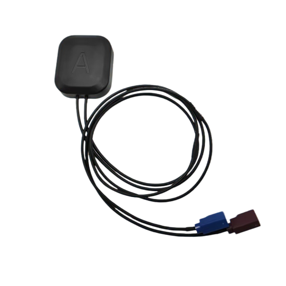

The modern automobile is undergoing a profound transformation, evolving from a purely mechanical machine into a sophisticated software-defined platform brimming with electronic control units (ECUs), sensors, and connectivity features. At the heart of this connected and increasingly autonomous vehicle revolution lies a critical, yet often overlooked, component: the Global Positioning System (GPS) antenna. However, this is not a generic antenna; it is a specialized device designed to meet the unique and stringent demands of the automotive environment. The most prevalent standard governing this component is the FAKRA (Fachkreis Automobil, or "Automotive Council") system, making the FAKRA GPS antenna a cornerstone of modern automotive telematics, infotainment, and advanced driver-assistance systems (ADAS).
A FAKRA GPS antenna is more than just an antenna; it is an integrated system comprising the radiating element, a Low-Noise Amplifier (LNA), and a standardized FAKRA connector, all housed within a package designed for vehicle integration. The FAKRA standard itself, originally developed by the German automotive industry and now a de facto global standard, defines a family of coaxial connectors that ensure interoperability, reliability, and correct pairing between antennas and receivers across different car manufacturers and suppliers. This standardization is crucial in an industry with complex, global supply chains.
The primary role of the automotive GPS antenna is to provide a reliable and continuous stream of position, velocity, and time (PVT) data to various vehicle systems. Its applications are diverse and critical:
Navigation: Providing the core location data for the onboard infotainment system's turn-by-turn navigation.
Telematics: Enabling emergency call systems (e.g., eCall in Europe, ERA-GLONASS in Russia), stolen vehicle tracking, remote diagnostics, and connectivity-based services.
Advanced Driver-Assistance Systems (ADAS): Serving as a key sensor for functions like adaptive cruise control, lane-keeping assistance, and automated parking by providing an absolute position reference. This is especially critical for systems that fuse GPS data with camera, radar, and LiDAR inputs.
Vehicle Intelligence: Time synchronization for event data recorders, timestamping of CAN bus data, and enabling location-based automation and personalization.
The automotive environment presents a uniquely hostile operating theatre for a sensitive RF component. Unlike a consumer device, an automotive antenna must perform flawlessly for over a decade while enduring extreme temperature cycles (-40°C to +85°C+), constant vibration, exposure to humidity, UV radiation, chemicals (like road salt), and physical impacts. Furthermore, it must do this while being placed in a suboptimal location—often embedded in a roof module, hidden in a fin, or integrated into a windshield—where its view of the sky is partially obstructed by the vehicle's own structure.
Moreover, the electromagnetic environment inside a modern car is incredibly noisy. The antenna must contend with interference from a multitude of sources: high-power cellular transmitters (4G/5G modems), Bluetooth and WiFi modules, switching power regulators, electric motor drives (in EVs), and countless digital processors. Despite these challenges, the antenna must reliably receive incredibly weak signals from satellites over 20,000 km away.
The FAKRA GPS antenna represents the automotive industry's engineered response to these challenges. It is a product of compromise and optimization, balancing RF performance, cost, durability, and aesthetics. Its overview reveals a component that is not an off-the-shelf consumer part, but a specialized, qualified, and highly reliable system essential for unlocking the safety, convenience, and connectivity features that define the modern driving experience.
The design and construction of a FAKRA GPS antenna are dictated by a rigid set of requirements from the automotive industry: extreme environmental resilience, consistent RF performance, high-volume manufacturability, and seamless integration into the vehicle's aesthetic and assembly process. Every material and design choice is a calculated compromise to meet these often competing demands.
The Radiating Element: Patches and PCBs
The core of the antenna is its radiating element. The most common types are:
Ceramic Patch Antenna: This is the most prevalent design for roof-mounted "shark-fin" modules. A square or circular patch of metallic material is printed on a ceramic substrate (e.g., Aluminum Oxide) with a high dielectric constant. This allows the patch to be physically small while remaining electrically resonant at the GPS L1 frequency (1575.42 MHz). The ceramic provides excellent temperature stability, ensuring consistent performance across the automotive temperature range.
Planar Inverted-F Antenna (PIFA): Commonly used when the antenna is integrated into a printed circuit board (PCB) within a larger module. The PIFA is a compact design that can be printed directly onto the PCB, saving cost and space. Its performance is highly dependent on the size and shape of the ground plane it is placed over.
FPC Antenna: Flexible Printed Circuit (FPC) antennas are used in applications where the antenna must conform to a specific curved surface, such as inside a vehicle's roof liner or a side mirror. They consist of a thin, flexible plastic substrate with a copper trace etched into the radiating pattern.
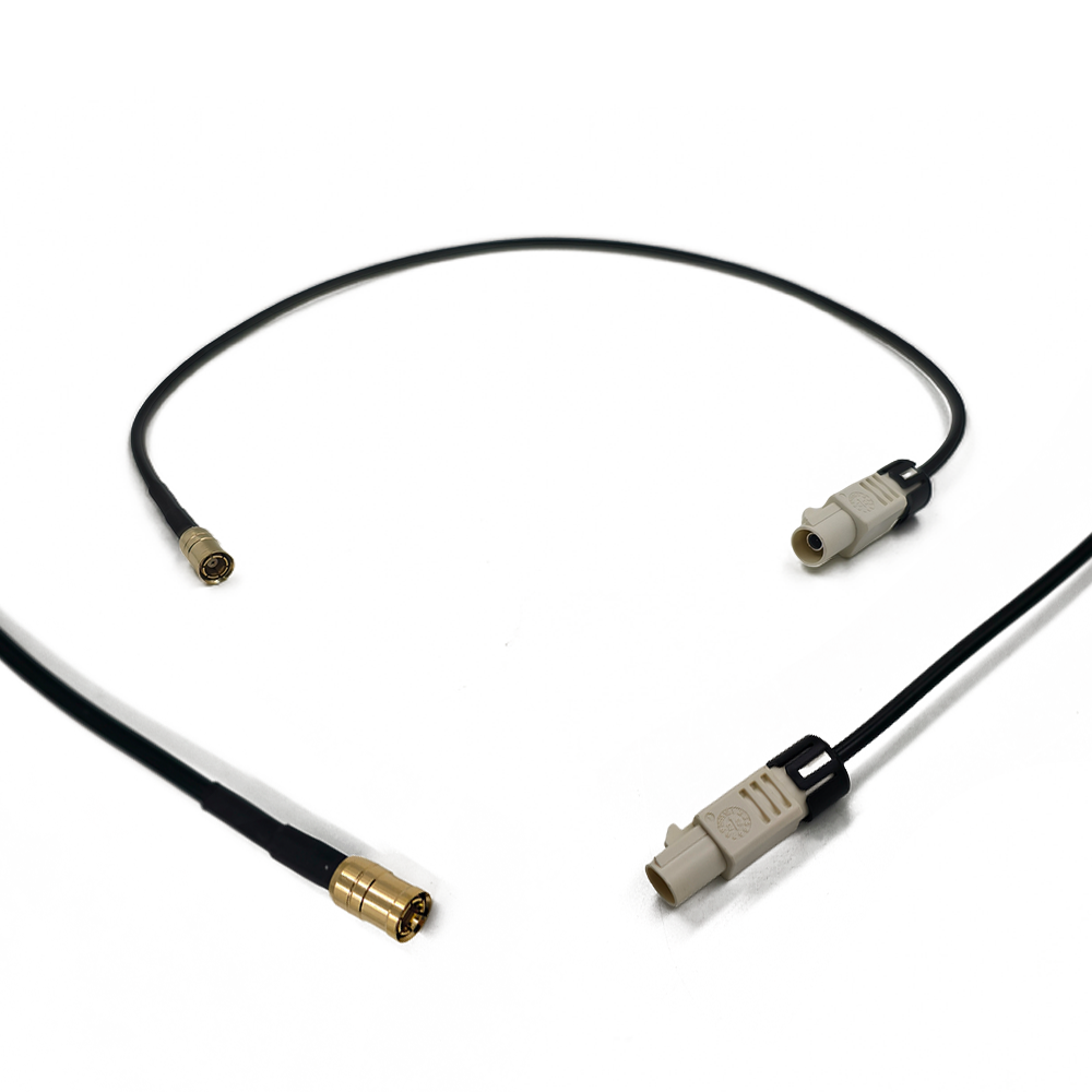
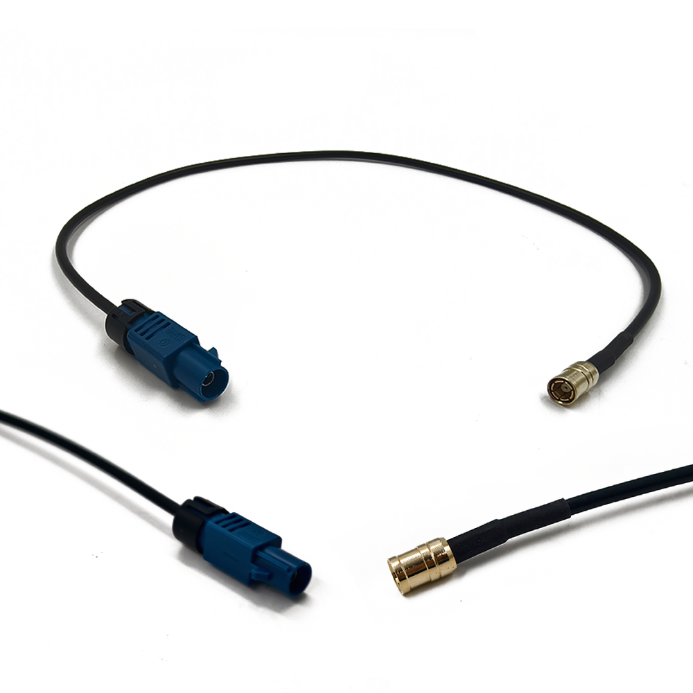
The FAKRA Connector: Standardization and Keying
The FAKRA connector is the defining external feature. It is more than just a connector; it is a system designed to prevent errors during the vehicle assembly process.
Color Coding: The blue housing is universally assigned to GPS/GNSS applications. This allows assembly line workers to quickly visually identify and connect the antenna to the correct port on the head unit or telematics control unit (TCU).
Mechanical Keying: Beyond color, each FAKRA connector type has a unique mechanical keying configuration (a specific arrangement of grooves and tabs). This physically prevents a GPS antenna from being plugged into a connector meant for, say, a cellular antenna (which would have a different color and keying), thus preventing damage and ensuring system integrity.
Performance: FAKRA connectors are designed to provide a stable 50-ohm impedance connection up to 6 GHz, ensuring minimal signal loss and reflection at GPS and other GNSS frequencies. They feature a robust locking mechanism to prevent vibration-induced disconnections.
The Active Component: Low-Noise Amplifier (LNA)
Virtually all automotive GPS antennas are active antennas. They incorporate a Low-Noise Amplifier (LNA) module positioned immediately after the radiating element. This LNA is crucial because:
It compensates for cable loss. The coaxial cable running from the roof to the infotainment unit can be several meters long, introducing significant signal attenuation. The LNA boosts the signal at the source, preserving the critical Signal-to-Noise Ratio (SNR) before any loss occurs.
It must be ultra-linear. The automotive RF environment is saturated with powerful signals. The LNA must have high linearity to avoid being overloaded or generating intermodulation products from these interfering signals, which would corrupt the weak GPS data.
It requires power. The LNA is powered by the receiver (head unit or TCU) through the same coaxial cable via a "bias-T" circuit, which injects DC voltage onto the RF line.
Housing and Environmental Protection
The antenna's housing is its first line of defense.
Roof-Mounted "Shark Fin": This is the most iconic form factor. The housing is typically made from high-grade, UV-stable polycarbonate or Polybutylene terephthalate (PBT) plastic that is painted to match the vehicle's roof. It must withstand direct sun exposure, hail, car washes, and extreme temperature cycling without cracking, fading, or deforming.
Environmental Sealing: The entire assembly is hermetically sealed, typically to an IP5K7 (dust-proof) and IPX7 (water immersion up to 1m) rating. This prevents moisture ingress, which would detune the antenna and cause corrosion and failure.
Adhesive and Mounting: Shark-fin antennas are primarily attached to the vehicle's roof using a thick, high-performance acrylic foam tape. This tape must create a permanent waterproof bond and withstand high shear forces from wind and car washes, while also accommodating the different thermal expansion rates of the plastic fin and the metal roof.
Filtering and EMI Mitigation
Given the noisy environment, the internal design must include mitigation strategies. This often involves integrating Surface Acoustic Wave (SAW) filters or Bulk Acoustic Wave (BAW) filters into the LNA module to reject strong out-of-band interference from cellular and other onboard transmitters, preventing them from overloading the receiver.
In summary, the construction of a FAKRA GPS antenna is a masterclass in designing a high-frequency electronic component for a brutal environment. It combines RF engineering, materials science, connector technology, and rigorous manufacturing quality control to create a device that is both a precision instrument and a durable automotive part.
The working principle of a FAKRA GPS antenna is a continuous process of capturing an incredibly weak signal, protecting it from a hostile environment, and delivering it faithfully to the receiver. It functions as a sensitive data acquisition node at the edge of the vehicle's network, and its operation is a blend of fundamental electromagnetics and sophisticated electronic conditioning.
Fundamental Signal Reception and the Role of the Ground Plane
The primary function of the radiating element (e.g., the ceramic patch) is to act as a transducer, converting the electromagnetic energy from GPS satellites into an electrical current. The antenna is designed to be most sensitive to Right-Hand Circularly Polarized (RHCP) waves, which is the polarization used by GPS satellites. This provides a inherent level of rejection to reflected signals that may have reversed polarization.
A critical, often unseen, part of the antenna system is the ground plane. For a roof-mounted shark-fin antenna, the vehicle's metal roof itself acts as the ground plane. The antenna's performance is heavily dependent on the size and quality of this ground plane. The roof provides a stable, conductive surface that:
Shapes the Radiation Pattern: It creates a directional pattern, focusing sensitivity towards the sky (where the satellites are) and providing some inherent rejection of signals arriving from low angles (which are often multipath reflections from the ground or other vehicles).
Provides a Electrical Reference: It serves as the counterpoise for the radiating element, essential for establishing the correct impedance and efficient radiation.
The absence of a sufficient ground plane (e.g., if the antenna were placed on a composite roof or a small patch of metal) would severely degrade performance, leading to a distorted radiation pattern and low gain.
Active Amplification: The Low-Noise Amplifier (LNA)
The signal induced in the antenna element is exceptionally weak, typically around -130 dBm. If this signal were sent directly down several meters of coaxial cable, the cable's inherent loss (attenuation) would degrade it to a level indistinguishable from noise by the time it reached the receiver.
This is where the integrated LNA performs its crucial role. Positioned as close as possible to the radiating element, the LNA amplifies the signal immediately, boosting its power by typically 25 to 30 dB. This pre-amplification ensures that the signal is strong enough to survive the journey through the cable with a usable Signal-to-Noise Ratio (SNR) intact. The "Low-Noise" aspect is critical; the amplifier itself must add as little additional electronic noise as possible, as any added noise cannot be separated from the desired signal later.
Power Delivery via Bias-Tee
The LNA requires a DC power source (usually 3-5V). Running a separate power wire would add cost, weight, and complexity. The elegant solution is a bias-Tee circuit.
At the receiver end (head unit/TCU), the bias-Tee injects a DC voltage onto the center conductor of the coaxial cable.
At the antenna end, another bias-Tee circuit separates this DC voltage from the RF signal. The DC power is routed to the LNA, while the clean RF signal (now amplified) continues down the line.
This system allows for a single cable to provide both power and data connectivity, simplifying installation and improving reliability.
Spectral Filtering: Combating Interference
The automotive EM spectrum is a crowded and noisy place. The most significant threat is desensitization from the vehicle's own powerful cellular modem, which can transmit signals billions of times stronger than the GPS signal.
To prevent this, the antenna assembly includes bandpass filters (typically SAW filters). These filters are extremely selective, acting like a precise gate that only allows frequencies in the GNSS band (e.g., 1559-1610 MHz) to pass through to the LNA and onward to the receiver. They aggressively attenuate all other frequencies, particularly those used by cellular networks (700 MHz, 800 MHz, 1.8 GHz, 1.9 GHz, 2.1 GHz, etc.), preventing them from overloading the sensitive amplifier and receiver electronics.
The FAKRA Connector: Ensuring Signal Integrity
Finally, the FAKRA connector ensures that this carefully preserved signal is transferred to the vehicle's wiring harness with minimal loss and reflection. Its consistent 50-ohm impedance and secure locking mechanism maintain the integrity of the RF path, preventing intermittent connections that could cause the navigation system to drop out.
In essence, the working principle of the FAKRA GPS antenna is a battle against physics: overcoming immense distances, cable loss, and a storm of interference to deliver a clean, amplified, and trustworthy signal that the vehicle's systems can use to confidently determine its place in the world.
The FAKRA system represents the automotive industry's engineered solution for RF connectivity, offering significant advantages for manufacturers, suppliers, and end-users. However, designing and implementing a GPS antenna within this framework presents a unique set of challenges that must be meticulously managed.
Advantages:
Standardization and Interoperability: This is the single greatest advantage. The FAKRA standard ensures that an antenna from one supplier will connect correctly and perform predictably with a receiver from another. This simplifies the supply chain, reduces engineering validation time, and fosters competition, ultimately driving down costs and encouraging innovation.
Error-Proof Assembly: The color-coding (blue for GPS) and mechanical keying system are invaluable on the high-speed automotive assembly line. They prevent misconnections (e.g., plugging the GPS antenna into the cellular modem port), which could lead to system malfunctions, damaged components, and costly rework or warranty claims.
Robustness and Reliability: FAKRA connectors are designed for the automotive environment. Their locking mechanism ensures a secure connection that is highly resistant to vibration-induced disconnection or signal degradation. This mechanical robustness is essential for a safety-critical system like eCall, which must work reliably even after a severe accident.
RF Performance: The connector is designed for high-frequency performance up to 6 GHz, providing low voltage standing wave ratio (VSWR) and minimal insertion loss. This ensures that the carefully amplified signal from the active antenna is delivered to the receiver with maximum fidelity.
Simplified Integration: The self-contained nature of the active FAKRA antenna module (element + LNA + connector) simplifies the vehicle integration process. The automotive OEM does not need to be an RF expert; they simply need to provide a clear "window" to the sky on the roof and route a cable to the head unit.
Challenges and Limitations:
The Hostile Automotive RF Environment: This is the paramount challenge. The antenna and its LNA must operate flawlessly in the presence of powerful interferers, primarily the vehicle's own cellular modem. Preventing desense (where the cellular transmitter desensitizes the GPS receiver) requires excellent filtering, careful spectral management, and often physical separation within the vehicle, which is difficult to achieve in a compact platform.
Suboptimal Antenna Placement and Ground Plane: While the roof is the best location, it is not perfect. The vehicle's structure (A-pillars, sunroof mechanisms) can create partial obstructions. Furthermore, the size of the ground plane (the roof) is fixed and can electrically detune the antenna depending on the specific placement of the shark fin. The trend towards panoramic glass roofs and composite materials also threatens to remove the ideal metallic ground plane altogether, forcing a redesign of antenna systems.
Multipath Interference: Urban canyons, bridges, and even the vehicle's own body can cause multipath signals. While the antenna's ground plane helps, automotive antennas lack the sophisticated multipath rejection capabilities of survey-grade choke rings. The receiver's algorithms must do most of the work to mitigate these errors.
Stringent Cost and Space Constraints: Every component in a vehicle is subject to extreme cost pressure. The antenna must deliver high performance at the lowest possible cost. Furthermore, real estate on the vehicle roof is highly contested, with a single shark fin often needing to house not only GPS, but also antennas for cellular (4G/5G), satellite radio (SDARS), WiFi, Bluetooth, and even V2X communications. This creates a crowded environment where antenna elements can couple with each other, degrading performance.
Extreme Environmental Durability Requirements: The antenna must survive and perform consistently for 10-15 years while exposed to a brutal combination of factors: temperature cycling from Arctic cold to desert heat, UV radiation that degrades plastics, humidity that promotes corrosion, and mechanical shock and vibration that can fracture solder joints and connections.
Cable Loss and Complexity: While the LNA compensates for it, the long cable run still introduces some loss and is a cost and weight item. Furthermore, the wiring harness itself is a complex part, and adding another cable increases assembly time and potential for errors.
In conclusion, the advantages of the FAKRA system—standardization, robustness, and error-proofing—make it an indispensable part of the automotive industry. The challenges are significant and inherent to the application, requiring continuous innovation in RF design, materials science, and system architecture to ensure that the humble GPS antenna can continue to meet the escalating demands of the connected car.
The FAKRA GPS antenna is a critical enabler for a wide array of functions that define the modern connected vehicle. Its applications extend far beyond simple navigation, forming the foundation for safety, security, and future autonomous functionalities. As the automotive industry evolves, so too does the role and technology of this essential component.
Core Applications:
In-Vehicle Navigation: This is the most visible application. The antenna provides the precise location data required for the turn-by-turn guidance displayed on the infotainment screen. The reliability of this function is a key customer satisfaction point.
Emergency Call Systems (eCall/ERA-GLONASS): This is a safety-critical application. In the event of a serious accident, the telematics control unit (TCU) uses the GPS antenna to get the vehicle's precise coordinates and automatically dials emergency services, transmitting the location to drastically reduce response times. The reliability and availability of the GPS signal here is literally a matter of life and death.
Stolen Vehicle Tracking and Recovery: Many vehicles are equipped with systems that can report their location to a monitoring center if stolen. This allows law enforcement to recover the vehicle quickly. This requires the antenna to be able to provide a location even in challenging conditions.
Telematics and Connected Services: Services like GM's OnStar, Ford's SYNC Connect, and BMW ConnectedDrive rely on the GPS antenna for remote diagnostics, remote door unlock, vehicle status reporting, and providing traffic information and concierge services based on the vehicle's location.
Advanced Driver-Assistance Systems (ADAS): While cameras and radar provide relative positioning, GPS provides the absolute geographical context. This is crucial for:
Intelligent Speed Assistance: Using GPS location to know the local speed limit.
Adaptive Cruise Control and Lane Keeping: Providing context for highway vs. urban driving.
Automated Parking: Helping to locate the vehicle within a parking lot map.
Predictive Powertrain Control: Using map and location data to optimize gear shifting and energy usage in hybrids and EVs.
Future Trends:
Transition to Multi-Band GNSS: The next generation of automotive antennas will need to receive more than just GPS L1. Support for multi-constellation (Galileo, GLONASS, BeiDou) and multi-frequency signals (e.g., L5) is becoming essential. L5 signals are stronger, more robust, and allow for much better ionospheric error correction, which will improve accuracy from meter-level to decimeter-level. This is a prerequisite for higher levels of autonomy.
Integration into "Multi-Function" Antenna Modules: The standalone shark fin for GPS is disappearing. The future is the "multi-antenna" or "antenna farm" module. A single roof fin will integrate radiating elements for GPS, 4G/5G cellular, V2X (DSRC or C-V2X), WiFi, Bluetooth, and satellite radio. This presents immense design challenges in minimizing interference between these closely packed elements.
The Rise of "Antenna-in-Glass": To address the loss of metal roofs and the aesthetic desire for cleaner vehicle designs, antennas are being directly embedded into the vehicle's glass. Heater lines and defroster elements on the rear window are often used as radiating elements for AM/FM, while GPS and other higher-frequency antennas can be printed using transparent conductive films on windshields and windows.
Dead Reckoning and Sensor Fusion: Recognizing that GPS signals can be lost in tunnels, urban canyons, and parking garages, systems are increasingly fusing GPS data with inertial measurement unit (IMU) data (accelerometers and gyroscopes) and wheel speed sensors. This allows the vehicle to "dead reckon" and maintain a position fix during short GPS outages. The antenna is a key input into this fused navigation solution.
Standardization beyond FAKRA: H-MTD and AKD: FAKRA connectors are relatively large. As the number of antennas grows, their space and weight become problematic. The industry is moving towards smaller, more modular connector systems like H-MTD (High-Speed Data Transmission) and AKD (Automotive Keystone Docking) to accommodate the higher number of connections in a smaller space.
Enhanced Cybersecurity: As the GPS signal becomes more critical for safety, it also becomes a target for spoofing (broadcasting fake GPS signals to mislead the vehicle). Future systems may incorporate antenna-level features or additional sensors to help detect and mitigate such attacks.
The FAKRA GPS antenna is at a crossroads, evolving from a single-function component into an integrated element of a complex vehicle connectivity and sensing hub. Its future is one of greater capability, tighter integration, and increased importance as a fundamental sensor for the autonomous driving era.
Conclusion
The FAKRA GPS antenna is a paradigm of automotive engineering: a component that appears simple on the surface but embodies a deep complexity born from the need to deliver unwavering reliability under the most demanding conditions. It is a critical nexus point where the digital world of satellite navigation meets the harsh physical reality of the automobile. Its role has expanded from enabling a convenience feature to becoming a foundational sensor for safety, security, and the incremental journey toward vehicle autonomy.
The success of the FAKRA system lies in its elegant solution to the automotive industry's core needs: standardization, quality, and reliability. The blue connector is more than a piece of plastic; it is a symbol of interoperability that simplifies manufacturing, reduces errors, and ensures that a critical system performs as intended for the life of the vehicle. This standardization has been instrumental in allowing GPS technology to proliferate from luxury models to become a standard feature across the entire automotive market.
However, the path forward is one of increasing challenge. The electromagnetic environment within a vehicle is becoming more crowded and hostile, while the performance demands from new ADAS and autonomous driving functions are becoming more stringent. The industry is pushing against the physical limitations of antenna placement, ground plane availability, and the sheer number of RF systems that must coexist on a single platform.
The future of the automotive GPS antenna is not one of obsolescence but of transformation. It will evolve from a standalone, single-purpose component into an integrated element of a centralized, multi-function RF hub. It will need to embrace multi-band, multi-constellation GNSS to provide the requisite accuracy and robustness. Its performance will be inextricably linked with advanced sensor fusion algorithms that blend its absolute position data with inertial and other sensor data to create a continuous and resilient navigation solution.
In conclusion, the FAKRA GPS antenna is a testament to the fact that in the world of high-tech automotive innovation, there are no insignificant parts. It is a masterpiece of compromise and optimization, balancing RF performance, cost, durability, and manufacturing efficiency. As cars become more connected and intelligent, this unassuming component will continue to sit quietly on the roof, performing its essential duty: telling the vehicle exactly where it is in the world, and in doing so, enabling a safer and more efficient future for mobility.

 86 0755 2819 9597
Lucy Yang | lucy.y@toxutech.com
Nicole Li | nicole@toxutech.com
Dotty Zhao | sales04@toxutech.com
Global Business Director / Sales Team / Global Operations


 En
En Cn
Cn Korean
 Home >


