

-
Products -PCBA Manufacturing RF Connectors RF Cable Assemblys Embedded Antennas External Antennas Positioning Chips and Modules
RF Connectors

RF Cable Assemblys
Embedded Antennas
External Antennas
Positioning Chips and Modules


 Language


Language


In the field of geospatial surveying and mapping, the demand for high - precision positioning has been constantly increasing. Global Navigation Satellite System (GNSS) technology has become the cornerstone of modern surveying, and the dual - frequency GNSS survey antenna, as a key component of GNSS receivers, plays a vital role in achieving accurate and reliable positioning results. Unlike single - frequency antennas that only receive signals from one frequency band, dual - frequency GNSS survey antennas are designed to simultaneously capture signals from two different frequency bands of GNSS satellite constellations. This unique capability gives them significant advantages in various surveying applications, ranging from land surveying and topographic mapping to infrastructure construction and geological monitoring.
The development of precision GNSS survey antennas is closely tied to the evolution of GNSS technology itself. The initial deployment of the Global Positioning System (GPS) by the United States in the 1970s marked the beginning of a new era in positioning. Early GPS - based surveying systems, while revolutionary at the time, had limitations in terms of accuracy and coverage. However, over the past few decades, significant advancements in satellite technology, signal processing algorithms, and antenna design have transformed the field. Today, precision GNSS survey antennas can leverage multiple satellite constellations, including GPS, Galileo (European Union), GLONASS (Russia), and BeiDou (China), as well as regional systems like QZSS (Japan) and IRNSS (India). This multi - constellation capability greatly enhances the number of available satellites, improves signal availability in challenging environments such as urban canyons and dense forests, and ultimately boosts positioning accuracy and reliability.
The global market for precision GNSS survey equipment, including antennas, has experienced steady growth in recent years. According to a report by MarketsandMarkets, the global GNSS survey equipment market is projected to reach a value of over $10 billion by 2027, with a compound annual growth rate (CAGR) of approximately 8% during the forecast period. This growth is driven by several factors, including the increasing demand for high - precision mapping in the construction and mining industries, the expansion of smart city initiatives that require detailed geospatial data for urban planning and management, and the growing adoption of precision agriculture techniques that rely on accurate positioning for tasks such as variable - rate fertilization and crop mapping.
Different surveying applications have distinct requirements for precision GNSS survey antennas. For example, in deformation monitoring of large structures like dams, bridges, and skyscrapers, the antenna must be capable of detecting extremely small changes in position over time, often on the order of millimeters. This requires the antenna to have exceptional stability and low noise performance. In contrast, in cadastral surveying, which involves defining and mapping property boundaries, the antenna needs to provide high absolute positioning accuracy to ensure the legal validity of the survey results. Additionally, in marine surveying, the antenna must be able to withstand harsh environmental conditions such as saltwater corrosion, high winds, and vibrations, while still maintaining reliable signal reception.
2.1 Antenna Types for Dual - frequency GNSS Survey
Choke Ring Antennas: Choke ring antennas are widely regarded as the gold standard for high - precision dual - frequency GNSS surveying. They consist of a central radiating element, typically a patch or helical antenna, surrounded by a series of concentric conductive rings (chokes). The primary function of these choke rings is to suppress multipath signals, which are reflected signals that can interfere with the direct GNSS signals and cause positioning errors. The choke rings work by creating a high - impedance boundary that prevents the reflected signals from reaching the central radiating element. This design significantly reduces the impact of multipath effects, making choke ring antennas ideal for applications such as geodetic surveying, where sub - centimeter level accuracy is required.
Choke ring antennas are usually designed to operate at two or more frequency bands. For example, a common dual - frequency choke ring antenna may support GPS L1/L2, Galileo E1/E5b, and GLONASS G1/G2 bands. The central radiating element is optimized to receive signals from both frequency bands, while the choke rings are sized and spaced to provide effective multipath suppression across these bands. The construction of choke ring antennas often involves the use of high - quality materials, such as aluminum or brass for the choke rings and a low - loss dielectric substrate for the radiating element, to ensure optimal performance and durability.
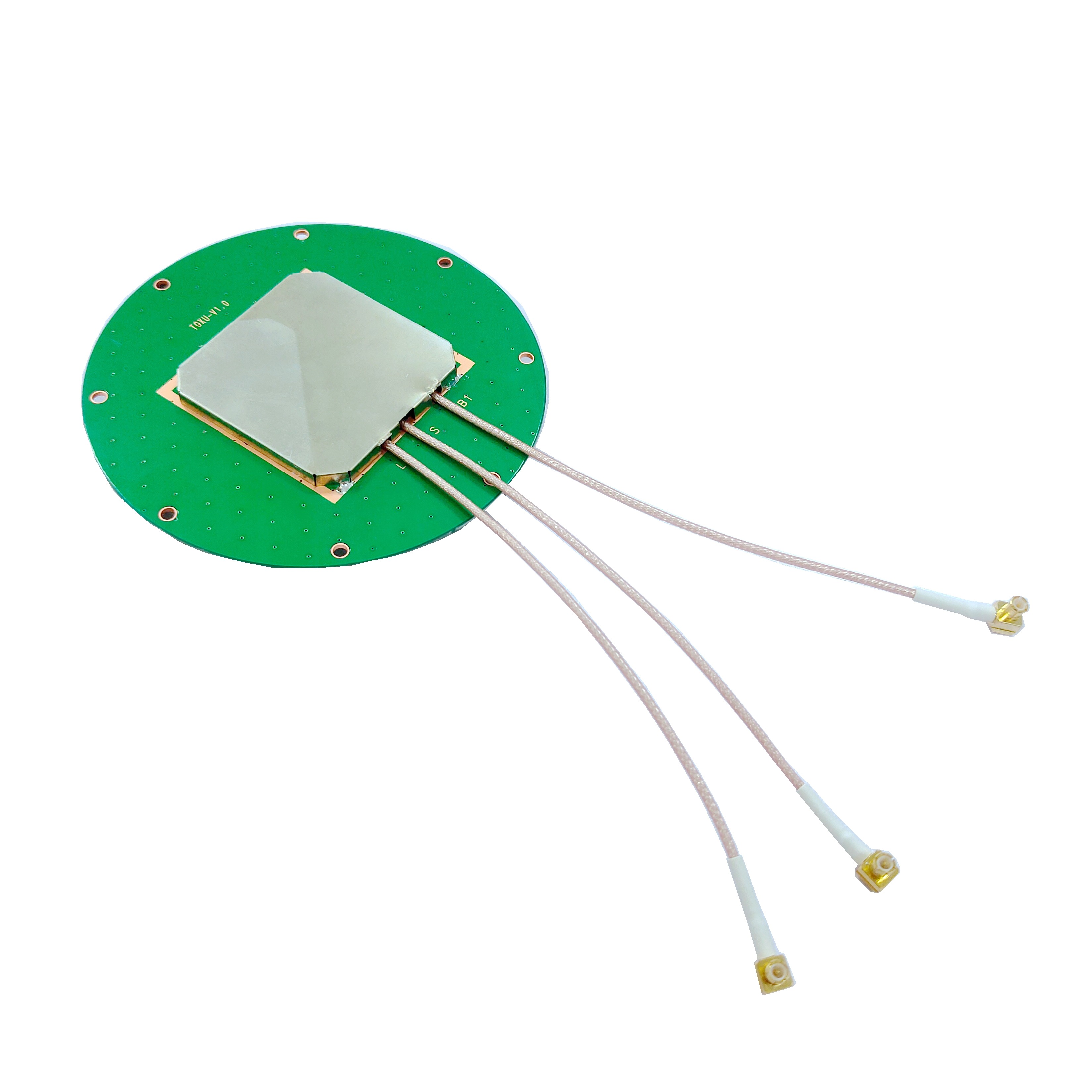
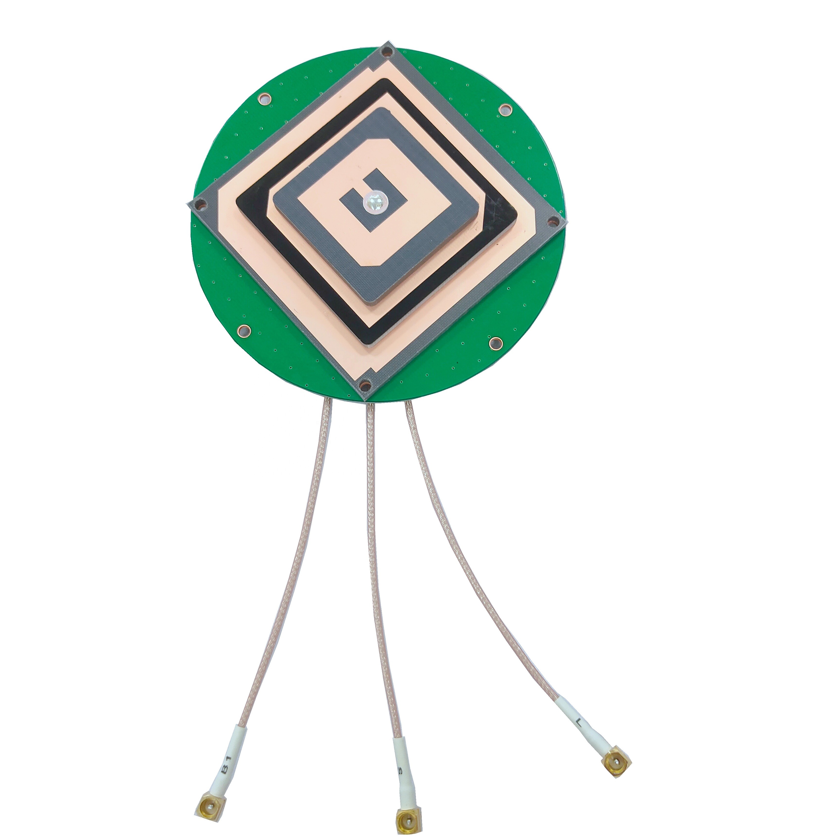
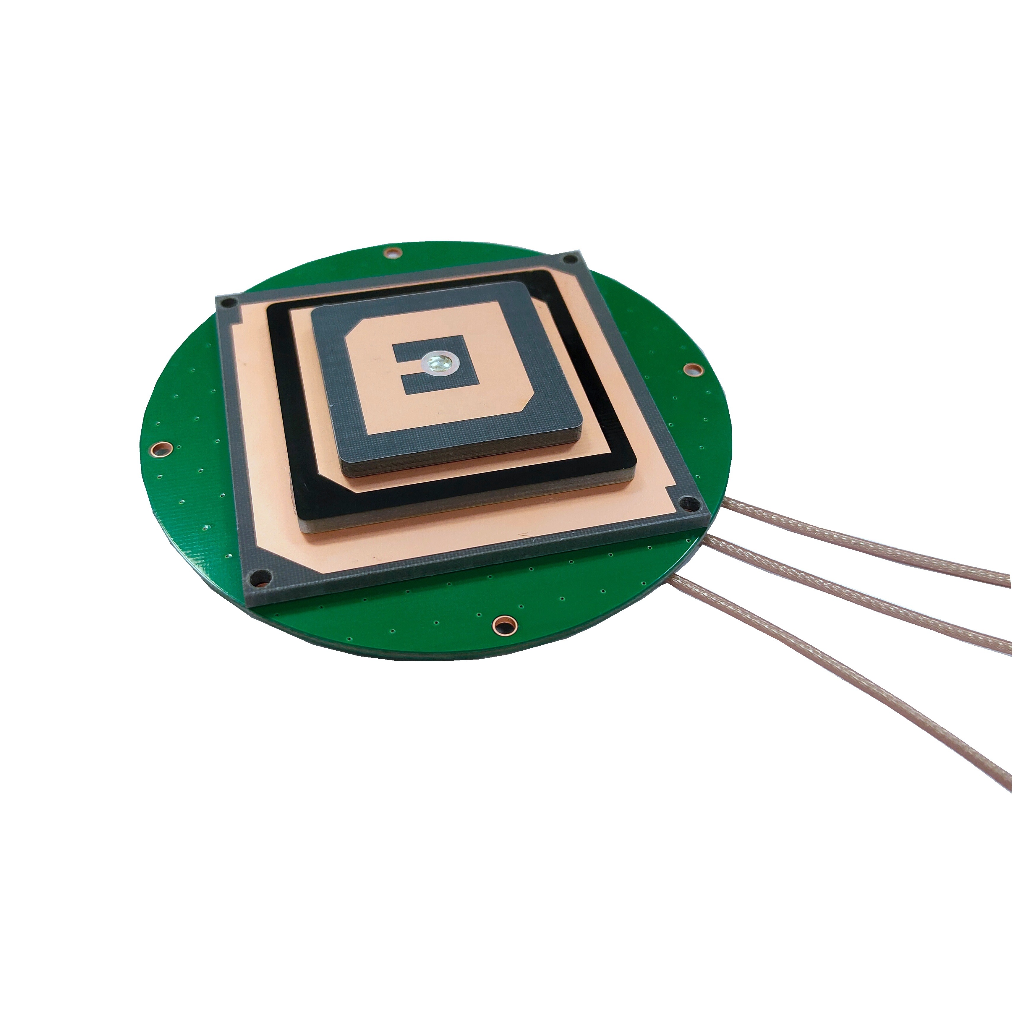
Patch Antennas: Patch antennas are another popular choice for dual - frequency GNSS survey applications, especially when compact size and low weight are important. A dual - frequency patch antenna typically consists of a flat, rectangular or circular metallic patch printed on a dielectric substrate, with a ground plane on the opposite side of the substrate. To achieve dual - frequency operation, the patch can be designed with specific geometric features, such as slots, notches, or a stacked structure. For example, a slot - loaded patch antenna can be designed to resonate at two different frequencies by introducing slots of appropriate dimensions into the patch. Alternatively, a stacked patch antenna uses two or more overlapping patches, each tuned to a different frequency band, to achieve dual - frequency reception.
Patch antennas offer several advantages for surveying applications. Their low - profile design allows for easy integration into portable surveying equipment, such as handheld GNSS receivers or UAV - mounted systems. They also have a relatively low cost compared to choke ring antennas, making them a cost - effective option for many surveying tasks. However, patch antennas are more susceptible to multipath effects than choke ring antennas, which can limit their accuracy in highly reflective environments. To mitigate this issue, some dual - frequency patch antennas incorporate additional features, such as a ground plane with slots or a cavity - backed design, to improve multipath rejection.
Helical Antennas: Helical antennas are less commonly used in dual - frequency GNSS surveying but can be a viable option in certain applications. A helical antenna consists of a metallic wire wound into a helical shape, with a ground plane at the base. The number of turns, the pitch (distance between adjacent turns), and the diameter of the helix determine the antenna's operating frequency, gain, and radiation pattern. For dual - frequency operation, a helical antenna can be designed with a variable pitch or a combination of two helices of different dimensions, each tuned to a specific frequency band.
Helical antennas offer good circular polarization, which is essential for receiving GNSS signals, as most GNSS satellites transmit circularly polarized signals. They also have a relatively wide bandwidth and can provide high gain in the direction of the helix axis. However, helical antennas are typically larger and heavier than patch antennas, which can make them less suitable for portable surveying equipment. They are more commonly used in fixed - site surveying applications, such as reference stations, where size and weight are not major constraints.
2.2 Materials Used in Construction
Dielectric Substrates: The dielectric substrate is a critical component of dual - frequency GNSS survey antennas, especially patch and helical antennas. It provides mechanical support for the radiating element and affects the antenna's electrical performance, such as its resonant frequency, bandwidth, and loss. Common dielectric materials used in these antennas include FR - 4 (Flame Retardant 4), Rogers substrates, and ceramic materials. FR - 4 is a widely used dielectric material due to its low cost, good mechanical strength, and ease of processing. However, it has a relatively high loss tangent, which can lead to signal attenuation and reduced antenna efficiency, making it less suitable for high - precision applications.
Rogers substrates, such as Rogers 4350B and Rogers 5880, are high - performance dielectric materials that offer low loss tangent, stable dielectric constant over a wide frequency range, and good thermal conductivity. These properties make them ideal for dual - frequency GNSS survey antennas, where high accuracy and reliability are required. Ceramic materials, such as alumina (Al₂O₃) and zirconia (ZrO₂), have even higher dielectric constants and lower loss tangents than Rogers substrates, allowing for the design of smaller antennas with high efficiency. However, ceramic materials are more brittle and expensive than other dielectric materials, which can limit their use in some applications.
Conductive Materials: The radiating elements, ground planes, and choke rings of dual - frequency GNSS survey antennas are typically made of conductive materials, such as copper, aluminum, and silver. Copper is the most commonly used conductive material due to its high electrical conductivity, good corrosion resistance, and ease of processing. It is often used for the radiating elements and ground planes of patch antennas, as well as the choke rings of choke ring antennas. Aluminum is a lighter and less expensive alternative to copper, but it has lower electrical conductivity and is more prone to corrosion. It is commonly used in applications where weight is a major concern, such as UAV - mounted antennas.
Silver has the highest electrical conductivity of all metals, making it an ideal material for high - performance antennas. However, silver is expensive and prone to tarnishing, which can reduce its conductivity over time. As a result, silver is often used as a coating on copper or aluminum surfaces to improve conductivity without significantly increasing the cost. For example, a patch antenna's radiating element may be made of copper with a thin silver coating to enhance signal reception and reduce losses.
Enclosure Materials: The enclosure of a dual - frequency GNSS survey antenna protects the internal components from environmental factors such as rain, dust, humidity, and extreme temperatures. Common enclosure materials include plastic, fiberglass, and aluminum. Plastic enclosures, such as those made of ABS (Acrylonitrile Butadiene Styrene) or polycarbonate, are lightweight, low - cost, and easy to mold into complex shapes. They provide good protection against dust and water (when properly sealed) and are suitable for most surveying applications.
Fiberglass enclosures offer better mechanical strength and resistance to extreme temperatures than plastic enclosures. They are also non - conductive, which helps to minimize interference with the antenna's signal reception. Fiberglass enclosures are commonly used in harsh environments, such as construction sites or remote surveying locations, where the antenna may be exposed to rough handling or extreme weather conditions. Aluminum enclosures provide excellent protection against impact and corrosion, but they are more expensive and heavier than plastic or fiberglass enclosures. They are often used in high - precision reference station antennas, where durability and long - term reliability are critical.
2.3 Manufacturing Processes
Printed Circuit Board (PCB) Fabrication: For patch antennas, the manufacturing process typically involves PCB fabrication techniques. The first step is to design the antenna's layout using computer - aided design (CAD) software, which defines the shape and dimensions of the radiating element, ground plane, and any additional features such as slots or notches. The layout is then printed onto a copper - clad dielectric substrate using photolithography. In this process, a photosensitive resist is applied to the copper surface, exposed to UV light through a mask of the antenna layout, and developed to remove the resist from the areas where the copper will be etched away. The substrate is then etched in a chemical solution to remove the unwanted copper, leaving behind the desired radiating element and ground plane.
After etching, the antenna may undergo additional processes, such as drilling holes for mounting or connecting to the receiver, and applying a protective coating to prevent corrosion. For dual - frequency patch antennas with a stacked structure, multiple PCB layers are fabricated and bonded together using an adhesive or lamination process. Each layer contains a radiating element tuned to a specific frequency band, and the layers are aligned to ensure proper electrical connection between the elements.
Choke Ring Fabrication: The fabrication of choke ring antennas involves the manufacturing of the central radiating element and the concentric choke rings. The central radiating element, which can be a patch or helical antenna, is fabricated using the same PCB or helical winding techniques as described earlier. The choke rings are typically made of aluminum or brass and can be manufactured using extrusion, casting, or machining processes. Extrusion is a common method for producing choke rings with a uniform cross - section, such as rectangular or circular rings. The metal is pushed through a die of the desired shape to form a long strip, which is then cut into the required length and bent into a circular shape.
Casting is used for more complex choke ring designs, where the rings have non - uniform cross - sections or additional features. The molten metal is poured into a mold of the choke ring shape and allowed to cool and solidify. Machining is used to produce high - precision choke rings with tight tolerances. The metal is cut and shaped using lathes, mills, or CNC (Computer Numerical Control) machines to achieve the desired dimensions and surface finish. Once the choke rings are fabricated, they are attached to a base plate, and the central radiating element is mounted in the center of the rings. The entire assembly is then enclosed in a protective housing to shield it from the environment.
Quality Control and Testing: Quality control is an essential part of the manufacturing process for dual - frequency GNSS survey antennas to ensure that they meet the required performance specifications. Various tests are conducted during and after manufacturing to verify the antenna's electrical and mechanical properties. Electrical tests include measuring the antenna's S - parameters (scattering parameters), which describe the reflection and transmission of signals at different frequencies. The S₁₁ parameter, for example, measures the return loss, which indicates how much of the signal is reflected back from the antenna rather than radiated. A low return loss (typically less than -10 dB) indicates that the antenna is efficiently radiating the signal.
Other electrical tests include measuring the antenna's gain, radiation pattern, and axial ratio. The gain is a measure of the antenna's ability to focus the signal in a particular direction, while the radiation pattern shows how the antenna radiates signals in all directions. The axial ratio measures the quality of the antenna's circular polarization, with a low axial ratio (typically less than 3 dB) indicating good circular polarization. Mechanical tests include checking the antenna's dimensions, weight, and durability. The antenna is also subjected to environmental tests, such as temperature cycling, humidity testing, and vibration testing, to ensure that it can withstand the harsh conditions of surveying applications.
3.1 Signal Reception from Dual Frequencies
Dual - frequency GNSS survey antennas are designed to receive signals from two different frequency bands of GNSS satellites simultaneously. Each frequency band carries unique information that is used to calculate the receiver's position. For example, in the GPS system, the L1 frequency band (1575.42 MHz) is primarily used for civilian applications and carries a coarse - acquisition (C/A) code, while the L2 frequency band (1227.60 MHz) carries a precise (P) code and a military (Y) code. Galileo's E1 band (1575.42 MHz) carries a public regulated service (PRS) code and an open service (OS) code, while the E5b band (1207.14 MHz) carries an OS code and a safety - of - life (SOL) code.
When a dual - frequency antenna receives signals from these two bands, it converts the electromagnetic signals into electrical signals, which are then sent to the GNSS receiver for processing. The antenna's radiating element is responsible for capturing the signals, and its design is optimized to resonate at both frequency bands. For example, a dual - frequency patch antenna with a slot - loaded design has two resonant frequencies, one for each frequency band, allowing it to efficiently receive signals from both bands. The ground plane of the antenna helps to reflect the signals towards the radiating element and reduces interference from signals coming from below the antenna.
The antenna's bandwidth is another important factor in signal reception. The bandwidth must be wide enough to cover both frequency bands and any frequency variations caused by temperature changes or manufacturing tolerances. A wide bandwidth ensures that the antenna can receive signals from both bands without significant loss of signal strength. In addition, the antenna's impedance must be matched to the impedance of the coaxial cable that connects it to the receiver. Impedance matching minimizes signal reflection at the antenna - cable interface, ensuring that the maximum amount of signal power is transferred to the receiver.
3.2 Ionospheric Delay Correction
One of the key advantages of dual - frequency GNSS survey antennas is their ability to correct for ionospheric delays. The ionosphere is a layer of the Earth's atmosphere located between approximately 60 and 1000 km above the Earth's surface. It contains a large number of charged particles (ions and electrons) that are produced by the ionization of gases by solar radiation. These charged particles affect the propagation of GNSS signals by slowing them down and changing their direction, leading to delays in the signal arrival time at the receiver. The magnitude of the ionospheric delay depends on the frequency of the signal, with lower - frequency signals experiencing greater delays than higher - frequency signals.
Dual - frequency antennas take advantage of this frequency dependence to calculate and correct for the ionospheric delay. The GNSS receiver measures the time it takes for the signals from both frequency bands to travel from the satellite to the antenna. Let's denote the time delay for the higher - frequency signal (f₁) as τ₁ and the time delay for the lower - frequency signal (f₂) as τ₂. The ionospheric delay (τ_iono) for the higher - frequency signal can be calculated using the following formula:
τ_iono = (τ₂ - τ₁) * (f₁² / (f₂² - f₁²))
Once the ionospheric delay for the higher - frequency signal is calculated, it can be subtracted from the measured time delay to obtain the true time delay, which is free from ionospheric effects. This corrected time delay is then used to calculate the distance between the satellite and the receiver (pseudorange), which is a key parameter in determining the receiver's position.
The ionospheric delay correction process is performed in real - time by the GNSS receiver, allowing for continuous high - precision positioning. This correction is particularly important in applications such as geodetic surveying and RTK positioning, where sub - centimeter or centimeter - level accuracy is required.3.3 Tropospheric Delay Mitigation
While ionospheric delays are a major concern for GNSS positioning, tropospheric delays also contribute to positioning errors, especially in applications requiring high precision. The troposphere is the lowest layer of the Earth's atmosphere, extending from the Earth's surface up to approximately 12 km. Unlike the ionosphere, the troposphere is a non - ionized region composed of neutral gases, water vapor, and aerosols. GNSS signals traveling through the troposphere are affected by refraction, which causes the signals to bend and travel at a slightly slower speed than in a vacuum, leading to tropospheric delays.
Dual - frequency GNSS survey antennas, in combination with advanced receiver algorithms, play a role in mitigating tropospheric delays. Although tropospheric delays are not frequency - dependent (unlike ionospheric delays), the use of dual - frequency signals provides more data points for the receiver to model and correct these delays. The tropospheric delay can be divided into two components: the dry component and the wet component. The dry component is primarily caused by the neutral gases in the troposphere and is relatively stable and predictable. It can be modeled using mathematical equations based on parameters such as the receiver's altitude, latitude, and the time of day.
The wet component, on the other hand, is caused by water vapor in the troposphere and is highly variable, as water vapor content can change rapidly with time and location. This makes it more difficult to model and correct. Dual - frequency GNSS data can be used in conjunction with meteorological data (such as temperature, pressure, and humidity measurements) to improve the accuracy of tropospheric delay models. For example, the receiver can use the dual - frequency signal measurements to estimate the zenith tropospheric delay (ZTD), which is the total tropospheric delay along the vertical path. The ZTD can then be decomposed into the dry and wet components using meteorological data, and the wet component can be further corrected using techniques such as tomography or numerical weather prediction (NWP) models.
In addition, the use of multiple GNSS constellations (enabled by dual - frequency antennas) provides more satellite observations, which helps to reduce the uncertainty in tropospheric delay estimates. By combining data from GPS, Galileo, GLONASS, and Beidou, the receiver can obtain a more comprehensive set of measurements, allowing for a more accurate modeling of the troposphere and a reduction in positioning errors caused by tropospheric delays.
3.4 Multipath Signal Suppression
Multipath signals are another significant source of positioning errors in GNSS surveying. They occur when GNSS signals are reflected off nearby objects, such as buildings, trees, water bodies, or the ground, before reaching the antenna. These reflected signals can interfere with the direct signals, leading to errors in the measurement of the signal arrival time and, consequently, errors in the calculated position.
Dual - frequency GNSS survey antennas are designed with various features to suppress multipath signals. As mentioned earlier, choke ring antennas are particularly effective in this regard. The concentric choke rings around the central radiating element create a high - impedance boundary that prevents reflected signals from reaching the radiating element. The choke rings work by absorbing or reflecting the multipath signals, reducing their amplitude before they can interfere with the direct signals. The design of the choke rings, including the number of rings, their size, and their spacing, is optimized to provide effective multipath suppression across the two frequency bands supported by the antenna.
Patch antennas, while more susceptible to multipath than choke ring antennas, can also incorporate features to improve multipath rejection. For example, a cavity - backed patch antenna uses a metallic cavity behind the patch to reduce the reception of signals coming from below the antenna. The cavity acts as a shield, blocking reflected signals that would otherwise reach the patch from the ground or other low - lying objects. Another technique used in patch antennas is the use of a ground plane with slots or notches. These slots can be designed to absorb or redirect multipath signals, reducing their impact on the direct signal.
Helical antennas, with their directional radiation pattern, can also help to suppress multipath signals. The high gain in the direction of the helix axis means that the antenna is more sensitive to direct signals coming from satellites in the sky and less sensitive to reflected signals coming from lower angles. This directional 特性 reduces the likelihood of multipath signals being received and processed by the GNSS receiver.
In addition to the antenna design, the GNSS receiver also uses signal processing algorithms to further suppress multipath signals. For example, the receiver can use a technique called "narrow correlator spacing" to improve the discrimination between direct and multipath signals. Narrow correlator spacing reduces the width of the correlation peak used to measure the signal arrival time, making it less likely that multipath signals will be mistaken for direct signals. Another technique is "multipath mitigation filters," which use the dual - frequency signal data to identify and remove multipath - induced errors from the position calculations. By comparing the signal characteristics (such as amplitude, phase, and code delay) at the two frequencies, the receiver can detect the presence of multipath signals and apply corrections to reduce their impact.
4.1 Advantages
High - Precision Positioning: The most significant advantage of dual - frequency GNSS survey antennas is their ability to provide high - precision positioning. By receiving signals from two frequency bands, these antennas allow for the correction of ionospheric delays, which are a major source of error in single - frequency systems. This correction enables positioning accuracies of sub - centimeter to centimeter level, which is essential for applications such as geodetic surveying, cadastral mapping, and infrastructure construction. For example, in geodetic surveying, dual - frequency antennas are used to measure the positions of reference points with extremely high accuracy, which is necessary for monitoring tectonic plate movements, sea - level rise, and other geological phenomena.
In real - time kinematic (RTK) positioning, a popular technique in surveying, dual - frequency antennas play a crucial role. RTK systems use a base station and a rover receiver. The base station, equipped with a high - precision dual - frequency antenna, measures the GNSS signals and transmits correction data to the rover. The rover, also using a dual - frequency antenna, receives the correction data and applies it to its own measurements, enabling real - time positioning with centimeter - level accuracy. This is particularly useful in construction projects, where precise positioning is required for tasks such as laying out foundations, installing structural components, and aligning pipelines.
Improved Performance in Challenging Environments: Dual - frequency GNSS survey antennas offer improved performance in challenging environments where satellite visibility is limited or signal quality is poor. Urban canyons, dense forests, and high - latitude regions are typical examples of such environments. In urban canyons, tall buildings block or reflect GNSS signals, leading to a reduced number of visible satellites and increased multipath effects. Dual - frequency antennas, with their multi - constellation compatibility, can receive signals from more satellites (from GPS, Galileo, GLONASS, and Beidou), increasing the number of available measurements and improving the reliability of the positioning solution.
In dense forests, the canopy of trees can attenuate GNSS signals, making it difficult for single - frequency antennas to receive sufficient signal strength. Dual - frequency antennas, with their higher gain and better signal reception capabilities, can capture weaker signals, allowing for positioning in forested areas. In high - latitude regions, the number of visible GPS satellites is often limited due to the satellite orbits. However, GLONASS and Beidou satellites have orbits that provide better coverage at high latitudes, and dual - frequency antennas can receive signals from these constellations, ensuring reliable positioning in these regions.
Reduced Sensitivity to Ionospheric Disturbances: Ionospheric disturbances, such as solar flares and geomagnetic storms, can cause significant variations in the ionospheric electron density, leading to large ionospheric delays and positioning errors. Single - frequency GNSS systems are highly sensitive to these disturbances, as they cannot correct for the ionospheric delays. Dual - frequency GNSS survey antennas, on the other hand, can calculate and correct for ionospheric delays in real - time, making them less sensitive to ionospheric disturbances.
During a solar flare, the increased solar radiation ionizes more gases in the ionosphere, leading to a sudden increase in the electron density. This causes a significant increase in the ionospheric delay for single - frequency signals, resulting in positioning errors of several meters or more. Dual - frequency antennas, however, can measure the ionospheric delay using the two frequency bands and apply the necessary correction, reducing the positioning error to a few centimeters or less. Similarly, during geomagnetic storms, the ionosphere becomes highly disturbed, and dual - frequency antennas can maintain their positioning accuracy by continuously correcting for the changing ionospheric conditions.
Compatibility with Multiple GNSS Constellations: Modern dual - frequency GNSS survey antennas are designed to be compatible with multiple GNSS constellations, including GPS, Galileo, GLONASS, and Beidou. This compatibility provides several advantages, including increased satellite visibility, improved positioning reliability, and reduced susceptibility to satellite outages. By receiving signals from multiple constellations, the antenna can access a larger number of satellites at any given time, which is particularly beneficial in environments where satellite visibility is limited.
For example, in urban areas, where buildings block signals from some satellites, the ability to receive signals from multiple constellations ensures that there are still enough satellites available to calculate a reliable position. In addition, if a satellite in one constellation fails or is taken out of service, the antenna can continue to receive signals from other constellations, ensuring uninterrupted positioning. The compatibility with multiple constellations also allows for the use of advanced positioning techniques, such as precise point positioning (PPP), which uses data from multiple constellations to achieve high - precision positioning without the need for a base station.
4.2 Challenges
Higher Cost: One of the main challenges associated with dual - frequency GNSS survey antennas is their higher cost compared to single - frequency antennas. The design and manufacturing of dual - frequency antennas are more complex, requiring specialized components and processes. For example, the radiating element must be optimized to resonate at two frequency bands, and the antenna may require additional features such as choke rings or cavity - backed designs to suppress multipath signals. These factors increase the production cost of dual - frequency antennas, making them more expensive for users.
The higher cost of dual - frequency antennas can be a barrier to adoption, especially for small - scale surveying companies or individual users with limited budgets. Single - frequency antennas are often sufficient for applications that do not require high - precision positioning, such as basic land surveying or recreational use, and their lower cost makes them a more attractive option. However, as the demand for high - precision positioning increases and manufacturing technologies improve, the cost of dual - frequency antennas is expected to decrease over time, making them more accessible to a wider range of users.
Increased Complexity in Design and Integration: Dual - frequency GNSS survey antennas are more complex in design than single - frequency antennas. The need to support two frequency bands requires careful optimization of the antenna's geometry, materials, and components. For example, the dielectric substrate must have a stable dielectric constant over both frequency bands to ensure that the antenna's resonant frequency does not shift, and the conductive materials must have low loss to minimize signal attenuation.
Integrating dual - frequency antennas into surveying equipment can also be more challenging. The antenna must be properly aligned with the receiver to ensure optimal signal transfer, and the coaxial cable used to connect the antenna to the receiver must be designed to handle signals from both frequency bands with minimal loss. In addition, the surveying equipment must be compatible with the dual - frequency signals, requiring the receiver to have the necessary hardware and software to process the data from both frequency bands. This increased complexity can lead to longer development times and higher integration costs for surveying equipment manufacturers.
Power Consumption: Dual - frequency GNSS survey antennas, especially those with active components such as low - noise amplifiers (LNAs), can consume more power than single - frequency antennas. The LNA is used to amplify the weak GNSS signals received by the antenna before they are sent to the receiver. For dual - frequency antennas, the LNA must be designed to amplify signals from both frequency bands, which can require more power than a single - frequency LNA.
In portable surveying equipment, such as handheld GNSS receivers or UAV - mounted systems, power consumption is a critical factor. The higher power consumption of dual - frequency antennas can reduce the battery life of the equipment, requiring more frequent recharging or battery replacement. This can be a significant inconvenience for surveyors working in remote areas where access to power is limited. To address this issue, manufacturers are developing more power - efficient LNAs and antenna designs. For example, some dual - frequency antennas use low - power LNAs with advanced semiconductor technologies, such as gallium arsenide (GaAs) or silicon germanium (SiGe), which offer high gain and low power consumption.
Susceptibility to Interference: While dual - frequency GNSS survey antennas offer better performance in terms of error correction, they are still susceptible to interference from other radio frequency (RF) signals. The frequency bands used by GNSS systems are shared with other wireless technologies, such as mobile communication systems, Wi - Fi networks, and radar systems. Interference from these sources can disrupt the GNSS signals, leading to reduced signal quality and increased positioning errors.
For example, the GPS L1 frequency band (1575.42 MHz) is close to the frequency band used by some mobile communication systems (such as LTE Band 1, which operates at 1920 - 1980 MHz and 2110 - 2170 MHz), and harmonic interference from these systems can affect the reception of GPS L1 signals. Similarly, Wi - Fi networks operating at 2.4 GHz can cause interference with the GLONASS G3 frequency band (1602 MHz) due to harmonic emissions.
To mitigate interference, dual - frequency GNSS survey antennas often incorporate filters to reject out - of - band signals. However, these filters can add complexity and cost to the antenna design, and they may not be able to completely eliminate all interference sources. In addition, the increasing number of wireless devices and the deployment of new wireless technologies (such as 5G) are expected to increase the level of RF interference in the environment, making it more challenging to ensure reliable GNSS signal reception.
5.1 Applications
Geodetic Surveying: Geodetic surveying is a branch of surveying that focuses on measuring the Earth's shape, size, and gravitational field, as well as the positions of points on the Earth's surface. It requires extremely high - precision positioning, often at the sub - centimeter level. Dual - frequency GNSS survey antennas are essential tools in geodetic surveying, as they can provide the high accuracy required for these measurements.
In geodetic surveying, dual - frequency antennas are used to establish and maintain geodetic reference frames, which are coordinate systems used to define the positions of points on the Earth's surface. These reference frames are used for a wide range of applications, including mapping, navigation, and scientific research. For example, the International Terrestrial Reference Frame (ITRF) is a global geodetic reference frame that is maintained using data from GNSS, satellite laser ranging (SLR), and very long baseline interferometry (VLBI). Dual - frequency GNSS antennas are used to collect the GNSS data used to update and refine the ITRF.
Another application of dual - frequency antennas in geodetic surveying is the monitoring of tectonic plate movements. By measuring the positions of reference points located on different tectonic plates over time, geophysicists can study the motion of the plates and predict earthquakes and volcanic eruptions. Dual - frequency antennas provide the high - precision measurements needed to detect small movements (on the order of millimeters per year) of these reference points.
Cadastral Surveying: Cadastral surveying is the process of measuring and mapping the boundaries of land parcels to establish ownership and legal rights. It requires accurate positioning of boundary markers to ensure that the boundaries are clearly defined and legally enforceable. Dual - frequency GNSS survey antennas are widely used in cadastral surveying due to their ability to provide centimeter - level positioning accuracy.
In cadastral surveying, dual - frequency antennas are used to measure the coordinates of boundary markers, such as stakes or monuments. The surveyor sets up the antenna at the boundary marker and collects GNSS data for a period of time (typically a few minutes to an hour) to ensure that the measurements are accurate. The data is then processed using specialized software to calculate the precise coordinates of the marker. These coordinates are used to create cadastral maps, which show the boundaries of each land parcel and the ownership information.
Dual - frequency antennas are particularly useful in cadastral surveying in rural areas, where there may be few visible landmarks to use for traditional surveying methods. They can also be used in urban areas, where the high - precision positioning allows for the accurate measurement of boundary markers in tight spaces, such as between buildings.
Infrastructure Construction: The construction of large - scale infrastructure projects, such as highways, bridges, tunnels, and airports, requires precise positioning to ensure that the components are installed correctly and that the structure meets the design specifications. Dual - frequency GNSS survey antennas are used throughout the construction process, from the initial surveying and design phase to the final inspection and maintenance phase.
In the surveying and design phase, dual - frequency antennas are used to measure the topography of the construction site to create detailed site plans. The surveyor collects GNSS data to map the elevation, contours, and features of the site, such as rivers, trees, and existing buildings. This data is used by engineers to design the infrastructure project, ensuring that it is compatible with the site conditions.
During the construction phase, dual - frequency antennas are used to guide the installation of structural components. For example, in the construction of a bridge, the surveyor uses the antenna to position the bridge piers and girders with high accuracy. The antenna is mounted on a total station or a robotic surveying system, which allows the surveyor to control the position of the component in real - time. This ensures that the component is installed exactly where it is supposed to be, reducing the need for rework and improving the quality of the construction.
In the final inspection and maintenance phase, dual - frequency antennas are used to verify that the infrastructure project meets the design specifications. The surveyor measures the positions of key components,such as bridge decks, road surfaces, and tunnel linings, to ensure that they are within the acceptable tolerance levels. Any deviations from the design can be identified and corrected promptly, ensuring the safety and durability of the infrastructure.
Agricultural Surveying and Precision Agriculture: In recent years, the application of GNSS technology in agriculture has grown rapidly, driven by the need to improve crop yields, reduce input costs, and minimize environmental impact. Dual - frequency GNSS survey antennas play a key role in agricultural surveying and precision agriculture by providing high - precision positioning for a variety of tasks.
Agricultural surveying involves mapping the farmland to create detailed field maps, which include information such as soil type, topography, and crop distribution. Dual - frequency antennas are used to collect accurate GNSS data to create these maps. For example, a surveyor can use a dual - frequency antenna mounted on a UAV or a ground - based vehicle to measure the coordinates of different points in the field. This data is then used to generate a digital elevation model (DEM) of the field, which helps farmers to identify areas with poor drainage, soil erosion, or other issues that may affect crop growth.
In precision agriculture, dual - frequency antennas are used to guide agricultural machinery, such as tractors, harvesters, and sprayers, with high accuracy. This is known as precision guidance, and it allows farmers to perform tasks such as planting, fertilizing, and spraying with great precision. For example, a tractor equipped with a dual - frequency GNSS receiver and antenna can be programmed to plant seeds in straight rows with a spacing of just a few centimeters. This not only improves the efficiency of the planting process but also ensures that the seeds are planted at the optimal depth and spacing, leading to higher crop yields.
Dual - frequency antennas are also used in variable rate technology (VRT), which is a key component of precision agriculture. VRT involves applying inputs such as fertilizers, pesticides, and water at variable rates based on the specific needs of different areas of the field. By using dual - frequency GNSS data to map the variability of soil nutrients, moisture, and crop health, farmers can adjust the application rates of these inputs to match the specific requirements of each area. This reduces the amount of inputs used, lowers costs, and minimizes the environmental impact of agricultural operations.
Disaster Management and Emergency Response: Dual - frequency GNSS survey antennas are valuable tools in disaster management and emergency response, where accurate and timely positioning information is crucial for saving lives and minimizing damage. Natural disasters such as earthquakes, floods, hurricanes, and wildfires can cause significant damage to infrastructure and disrupt normal life. In such situations, dual - frequency antennas are used to assess the damage, coordinate rescue efforts, and support the recovery process.
After an earthquake, for example, dual - frequency antennas are used to measure the displacement of the Earth's surface. This information helps geophysicists to understand the magnitude and impact of the earthquake and to predict aftershocks. It also helps engineers to assess the damage to buildings, bridges, and other infrastructure and to determine which structures are safe to enter and which need to be demolished.
In flood situations, dual - frequency antennas are used to map the extent of the flooding. By collecting GNSS data from UAVs or boats equipped with dual - frequency antennas, emergency responders can create detailed flood maps that show the areas affected by the flood and the depth of the water. This information is used to evacuate people from affected areas, allocate resources such as food, water, and medical supplies, and plan the cleanup and recovery efforts.
During wildfires, dual - frequency antennas are used to track the movement of the fire. UAVs equipped with dual - frequency antennas and thermal imaging cameras can fly over the fire zone and collect data on the location and spread of the fire. This information is transmitted in real - time to the command center, where it is used to deploy firefighting resources and to guide evacuation routes.
5.2 Future Trends
Integration with Emerging Technologies: The future of dual - frequency GNSS survey antennas will see increased integration with other emerging technologies, such as artificial intelligence (AI), machine learning (ML), and the Internet of Things (IoT). AI and ML algorithms can be used to process the large amounts of GNSS data collected by dual - frequency antennas more efficiently and accurately. For example, AI - powered data processing can improve the accuracy of tropospheric and multipath delay corrections by learning from historical data and adapting to changing environmental conditions.
ML algorithms can also be used to optimize the performance of dual - frequency antennas. By analyzing the antenna's performance under different conditions, such as varying signal strengths, interference levels, and environmental factors, ML algorithms can adjust the antenna's parameters (such as gain, bandwidth, and polarization) in real - time to ensure optimal performance. This adaptive optimization will be particularly useful in dynamic environments where the conditions change rapidly, such as urban canyons or areas with high levels of RF interference.
The integration of dual - frequency GNSS survey antennas with IoT will enable the development of smart surveying systems. These systems will connect the antenna to a network of sensors, such as meteorological sensors, soil moisture sensors, and structural health monitoring sensors. The data from these sensors will be combined with the GNSS data to provide a more comprehensive understanding of the surveying environment. For example, in precision agriculture, the combination of GNSS data, soil moisture data, and weather data will allow farmers to make more informed decisions about irrigation, fertilization, and pest control.
Miniaturization and Portability: As technology advances, there will be a trend towards the miniaturization of dual - frequency GNSS survey antennas. Smaller and lighter antennas will be developed, making them more suitable for use in portable surveying equipment, such as handheld GNSS receivers, UAVs, and wearable devices. This miniaturization will not only improve the portability of the equipment but also reduce its power consumption, extending the battery life of portable devices.
Advancements in materials science and manufacturing technologies will drive this miniaturization. For example, the use of microelectromechanical systems (MEMS) technology will allow for the production of tiny, high - performance antennas. MEMS - based dual - frequency antennas can be fabricated using batch manufacturing processes, which will reduce the cost of production and make them more accessible to a wider range of users.
In addition to miniaturization, the future will see the development of more integrated surveying solutions. Dual - frequency GNSS antennas will be integrated with other components, such as cameras, LiDAR sensors, and inertial measurement units (IMUs), into a single, compact device. This integration will simplify the surveying process, as users will no longer need to carry multiple separate devices. For example, a UAV equipped with an integrated dual - frequency GNSS antenna, LiDAR sensor, and camera can collect both position data and 3D point cloud data in a single flight, reducing the time and effort required for surveying.
Enhanced Anti - interference Capabilities: With the increasing number of wireless devices and the deployment of new wireless technologies, the level of RF interference in the environment is expected to increase. To address this challenge, future dual - frequency GNSS survey antennas will be equipped with enhanced anti - interference capabilities.
One of the key developments in this area will be the use of adaptive beamforming technology. Adaptive beamforming uses an array of antenna elements to focus the antenna's radiation pattern towards the desired satellite signals and away from interfering signals. By adjusting the phase and amplitude of the signals received by each element in the array, the antenna can dynamically steer its beam to avoid interference. This technology will be particularly effective in urban areas and other environments with high levels of RF interference.
Another trend in anti - interference technology is the use of machine learning - based interference detection and mitigation. ML algorithms can be trained to recognize the characteristics of different types of interference signals, such as those from mobile communication systems, Wi - Fi networks, and radar systems. Once the interference is detected, the algorithm can apply appropriate mitigation techniques, such as filtering or beamforming, to reduce its impact on the GNSS signals.
In addition, future dual - frequency GNSS survey antennas may incorporate frequency agility technology. This technology allows the antenna to switch between different frequency bands or channels in real - time to avoid interference. For example, if the GPS L1 frequency band is experiencing high levels of interference, the antenna can switch to the Galileo E1 frequency band to maintain reliable signal reception.
Expansion of Compatibility with New GNSS Constellations and Signals: As new GNSS constellations are developed and existing ones are expanded, future dual - frequency GNSS survey antennas will need to be compatible with these new constellations and their signals. For example, the European Union's Galileo constellation is still being expanded, with new satellites being launched to improve coverage and performance. The Chinese Beidou Navigation Satellite System (BDS) is also continuing to expand its global coverage.
Future dual - frequency antennas will be designed to support the new frequency bands and signals of these constellations. For example, Galileo's E6 frequency band (1278.75 MHz) and Beidou's B3 frequency band (1268.52 MHz) are expected to be widely used in high - precision surveying applications. Dual - frequency antennas will be optimized to receive signals from these new bands, providing even higher accuracy and reliability.
In addition to supporting new constellations, future dual - frequency antennas will also be compatible with new types of GNSS signals, such as high - rate positioning signals and integrity signals. High - rate positioning signals will provide more frequent position updates, which is essential for applications such as dynamic surveying and real - time monitoring of fast - moving objects. Integrity signals will provide information about the reliability of the GNSS positioning solution, alerting users to any errors or anomalies in the data. This will be particularly important in safety - critical applications, such as aviation and maritime navigation.
Increased Focus on Energy Efficiency: As the use of portable and battery - powered surveying equipment increases, there will be a greater focus on energy efficiency in dual - frequency GNSS survey antennas. Future antennas will be designed to consume less power while maintaining high performance.
Advancements in semiconductor technology will play a key role in improving energy efficiency. The development of low - power, high - performance LNAs and other active components will reduce the power consumption of the antenna. For example, the use of complementary metal - oxide - semiconductor (CMOS) technology for LNAs can significantly reduce power consumption compared to traditional technologies such as GaAs.
In addition, energy - harvesting technologies may be integrated into dual - frequency GNSS survey antennas. These technologies can convert environmental energy, such as solar energy, wind energy, or thermal energy, into electrical energy to power the antenna and the associated surveying equipment. This will extend the battery life of portable devices and reduce the need for frequent recharging or battery replacement, making the equipment more suitable for use in remote areas.
Conclusion
Dual - frequency GNSS survey antennas have emerged as indispensable tools in the field of geospatial surveying and mapping, enabling high - precision positioning that is essential for a wide range of applications. Throughout this exploration, we have delved into the overview, design and construction, working principles, advantages and challenges, applications, and future trends of these antennas, gaining a comprehensive understanding of their role and significance in modern surveying.
From an overview perspective, dual - frequency GNSS survey antennas stand out by their ability to receive signals from two distinct frequency bands of multiple GNSS constellations. This capability addresses the critical issue of ionospheric delays, a major source of error in single - frequency systems, and lays the foundation for achieving sub - centimeter to centimeter - level positioning accuracy. Their compatibility with GPS, Galileo, GLONASS, and Beidou constellations further enhances their versatility, making them suitable for use in diverse environments and applications.
In terms of design and construction, the variety of antenna types, including choke ring, patch, and helical antennas, each with unique features, caters to different surveying requirements. Choke ring antennas excel in multipath suppression, making them ideal for high - precision geodetic surveying, while patch antennas offer compactness and cost - effectiveness for portable applications. The careful selection of materials, such as high - performance dielectric substrates and conductive materials, and the use of advanced manufacturing processes, ensure the antennas' performance, durability, and reliability.
The working principles of dual - frequency GNSS survey antennas revolve around effective signal reception, ionospheric delay correction, tropospheric delay mitigation, and multipath signal suppression. By leveraging the frequency dependence of ionospheric delays, these antennas enable accurate correction of this error source. Additionally, through the use of advanced receiver algorithms and integration with meteorological data, they mitigate tropospheric delays, and their design features and signal processing techniques suppress multipath signals, further improving positioning accuracy.
The advantages of dual - frequency GNSS survey antennas are evident in their high - precision positioning, improved performance in challenging environments, reduced sensitivity to ionospheric disturbances, and compatibility with multiple constellations. These advantages have made them indispensable in applications such as geodetic surveying, cadastral surveying, infrastructure construction, agricultural surveying, and disaster management. However, they also face challenges, including higher cost, increased design and integration complexity, power consumption, and susceptibility to interference, which need to be addressed to further expand their adoption.
Looking to the future, the prospects for dual - frequency GNSS survey antennas are promising. Integration with emerging technologies like AI, ML, and IoT will enhance their data processing capabilities and adaptability. Miniaturization and portability will make them more accessible for use in portable and wearable devices. Enhanced anti - interference capabilities will ensure reliable performance in increasingly crowded RF environments. Compatibility with new GNSS constellations and signals will open up new possibilities for high - precision positioning. And increased focus on energy efficiency will extend the battery life of portable equipment, making them more suitable for remote and long - duration surveys.
In conclusion, dual - frequency GNSS survey antennas have revolutionized the field of geospatial surveying, providing the high - precision positioning necessary for a wide range of critical applications. While challenges remain, ongoing technological advancements are continuously addressing these issues and expanding the capabilities of these antennas. As we move forward, dual - frequency GNSS survey antennas will continue to play a pivotal role in driving innovation in surveying and mapping, supporting the development of smart cities, precision agriculture, infrastructure 建设,and disaster management, and contributing to a more accurate and sustainable understanding of our world.

 86 0755 2819 9597
Lucy Yang | lucy.y@toxutech.com
Nicole Li | nicole@toxutech.com
Dotty Zhao | sales04@toxutech.com
Global Business Director / Sales Team / Global Operations


 En
En Cn
Cn Korean
 Home >


