

-
Products -PCBA Manufacturing RF Connectors RF Cable Assemblys Embedded Antennas External Antennas Positioning Chips and Modules
RF Connectors

RF Cable Assemblys
Embedded Antennas
External Antennas
Positioning Chips and Modules


 Language


Language


In the fast-evolving world of embedded electronics and navigation technology, the Custom GNSS Patch Antenna emerges as a versatile, space-efficient solution designed to deliver reliable positioning data in the most compact of devices. Tailored for integration into navigation modules, GNSS receivers, and OEM (Original Equipment Manufacturer) applications, this antenna combines a small form factor with critical performance attributes to meet the demands of modern electronics. With features such as IPX connectivity, a ceramic and PCB (FR4) construction, and a frequency range optimized for global navigation satellite systems, it represents a perfect blend of customization and functionality, proving that size does not have to compromise performance in precision navigation.
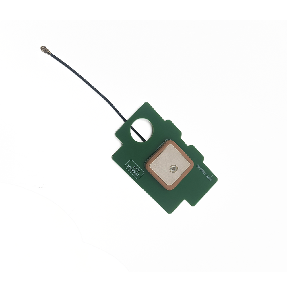
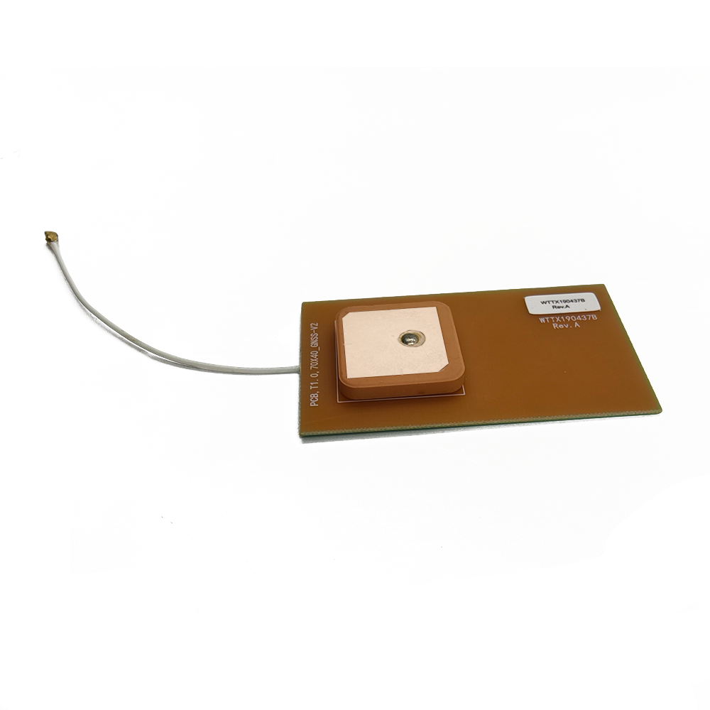
At the core of the Custom GNSS Patch Antenna’s design is its IPX connectivity, a feature that underscores its suitability for compact, embedded applications. IPX (also known as U.FL) connectors are among the smallest RF connectors available, measuring just a few millimeters in size, making them ideal for devices where space is at a premium. This miniature design allows the antenna to be integrated into tight spaces within navigation modules, wearables, and small IoT (Internet of Things) devices without adding significant bulk. The IPX connector’s snap-on mechanism ensures a secure connection, even in devices subject to minor vibrations or movement—common in portable electronics like handheld GPS units or drone controllers. Unlike larger connectors such as SMA, which require more space for mounting and cabling, IPX enables a streamlined integration process, reducing the overall footprint of the device. For OEMs, this means greater flexibility in product design, as the antenna can be placed in optimal locations (such as near the edge of a circuit board) to maximize signal reception without sacrificing the device’s aesthetic or functional design. The IPX connector also supports high-frequency signals up to several gigahertz, ensuring that the GNSS signals in the 1560-1602 MHz range are transmitted with minimal loss between the antenna and the receiver.
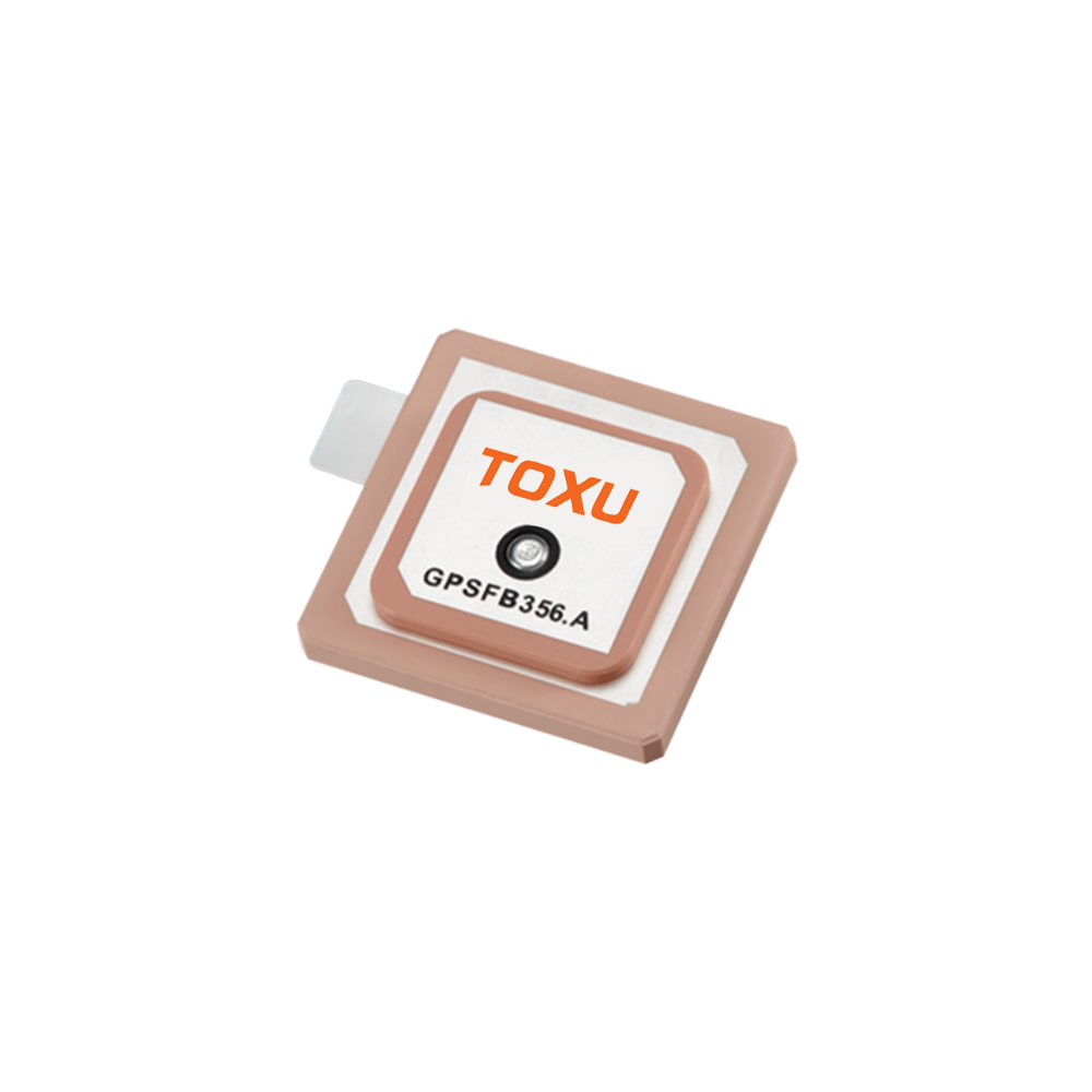
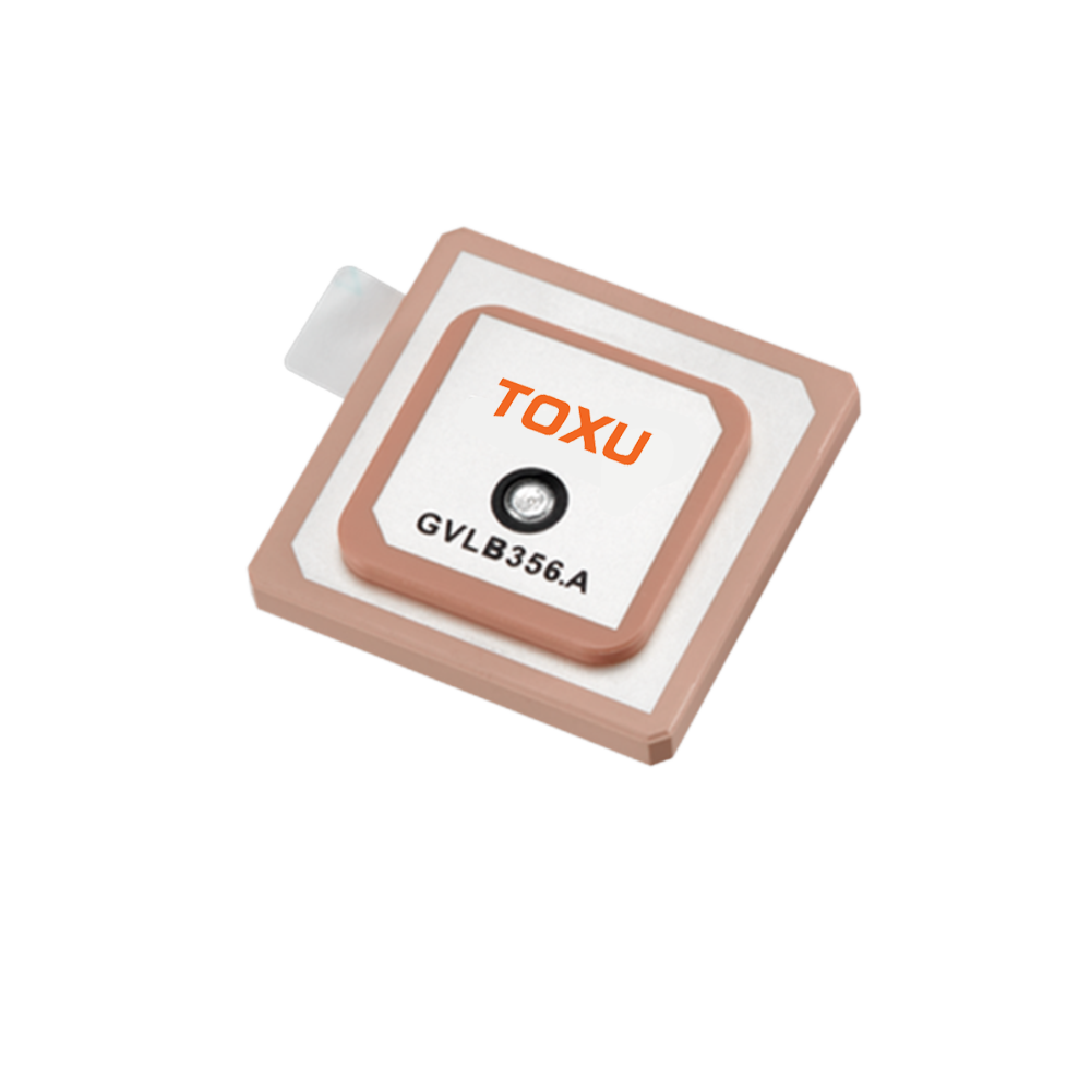
The antenna’s construction—combining a ceramic element with a PCB (FR4) substrate—reflects a deliberate focus on performance, durability, and manufacturability. The ceramic element, typically made from a high-dielectric-constant material such as barium titanate, serves as the radiating element of the antenna. Ceramic’s high dielectric constant allows the antenna to achieve resonance at GNSS frequencies (1560-1602 MHz) within a small physical size, a critical advantage for compact devices. This material also exhibits low loss at these frequencies, ensuring that the antenna efficiently converts electrical energy into radiated signals and vice versa. The PCB (FR4) substrate, a glass-reinforced epoxy laminate, provides a stable, rigid base for the ceramic element, simplifying manufacturing and ensuring consistent performance across production runs. FR4 is a standard material in electronics manufacturing, offering excellent mechanical strength, heat resistance, and electrical insulation properties. It also allows for easy integration of the antenna into existing PCB designs, as it can be soldered directly onto the device’s main circuit board or connected via the IPX cable. Together, the ceramic and FR4 construction creates an antenna that is both electrically efficient and mechanically robust, capable of withstanding the rigors of mass production and daily use in consumer and industrial electronics.
Linear polarization is a key design choice that aligns with the requirements of fixed or semi-fixed embedded applications. Unlike circular polarization, which is better suited for mobile devices where antenna orientation can vary (such as smartphones or drones), linear polarization offers higher efficiency when the antenna and satellite signals maintain a consistent alignment. In fixed applications—such as navigation modules mounted in the dashboard of a vehicle or a stationary IoT sensor—the antenna can be oriented to match the linear polarization of incoming GNSS signals, maximizing signal strength. This alignment is particularly important given the antenna’s modest gain of 1.5 dBi, as it ensures that the limited signal amplification is used effectively. Linear polarization also simplifies the antenna’s design, reducing complexity and cost—an important consideration for OEMs producing devices at scale. While linear polarization is more susceptible to signal degradation from reflections (compared to circular polarization), this is mitigated in fixed applications where the antenna’s orientation is controlled, making it a practical and cost-effective choice for embedded navigation systems.
The frequency range of 1560-1602 MHz positions the Custom GNSS Patch Antenna to support a wide range of global navigation satellite systems, enhancing its versatility and global compatibility. This band encompasses critical frequencies for major constellations: GPS L1 (1575.42 MHz), BeiDou B1 (1561.098 MHz), GLONASS G1 (1602 MHz), and Galileo E1 (1575.42 MHz). By covering this broad spectrum, the antenna ensures that devices can tap into multiple satellite networks, improving positioning accuracy and redundancy. For example, in regions where GPS signals may be weak due to atmospheric conditions or geographic obstacles, the antenna can rely on BeiDou or GLONASS signals to maintain a fix. This multi-constellation support is particularly valuable for OEMs producing devices for global markets, as it ensures consistent performance across different regions. The frequency range also future-proofs the antenna, as it is compatible with existing and upcoming GNSS upgrades, such as Galileo’s full operational capability and BeiDou’s global expansion. For navigation modules used in fleet tracking or logistics, this broad coverage ensures that vehicles and assets can be tracked reliably, whether in urban centers, remote rural areas, or international territories.
A typical gain of 1.5 dBi balances performance with the antenna’s compact size, making it suitable for applications where signal strength is prioritized but space constraints limit larger, higher-gain designs. Gain, measured in dBi (decibels relative to an isotropic radiator), indicates the antenna’s ability to focus signal energy in a specific direction. The 1.5 dBi gain of this antenna is optimized for the 1560-1602 MHz range, ensuring that it efficiently captures GNSS signals without requiring a large radiating element. This modest gain is sufficient for applications where the antenna has a clear view of the sky, such as in vehicle-mounted navigation modules or outdoor IoT sensors. In enclosed environments—such as the interior of a vehicle or a building—the antenna’s gain, combined with its efficient ceramic radiating element, helps compensate for signal attenuation caused by glass, plastic, or other materials. For OEMs, this balance between size and gain is critical, as it allows the antenna to be integrated into sleek, consumer-friendly devices without compromising the user’s ability to obtain a reliable GPS fix.
VSWR (Voltage Standing Wave Ratio) specifications of 2.0 at 1575 MHz and 3.5 at 1602 MHz provide insights into the antenna’s efficiency across its frequency range. VSWR measures the mismatch between the antenna and the connected cable or receiver, with lower values indicating better power transfer. At 1575 MHz (the primary GPS L1 frequency), a VSWR of 2.0 ensures that over 90% of the signal power is transferred, a high level of efficiency for a compact antenna. This is critical for maintaining strong GPS signals, which are essential for accurate positioning in most consumer and industrial applications. At 1602 MHz (GLONASS G1), a VSWR of 3.5 is acceptable given the antenna’s broad frequency coverage and the relatively lower usage of GLONASS in some regions. While this represents a higher level of signal reflection, it is balanced by the antenna’s ability to support multiple constellations, ensuring that users in regions relying on GLONASS still receive a usable signal. For OEMs, these VSWR values indicate that the antenna performs optimally at the most widely used GNSS frequencies while providing acceptable performance across the entire 1560-1602 MHz range, making it a versatile choice for global applications.
An impedance of 50 ohms aligns the antenna with industry standards for RF components, ensuring seamless compatibility with most GNSS receivers, modules, and coaxial cables. Impedance matching is critical for maximizing power transfer and minimizing signal reflection, which can cause interference and reduce the accuracy of positioning data. By adhering to the 50-ohm standard, the antenna can be integrated into existing electronic designs without the need for additional matching networks, simplifying the manufacturing process and reducing costs. This compatibility is particularly valuable for OEMs, who can incorporate the antenna into multiple product lines with minimal modifications. For example, a single antenna design can be used in both a handheld GPS unit and a vehicle tracking module, as both are likely to use 50-ohm receivers. The 50-ohm impedance also ensures that the IPX connector and RF1.37mm coaxial cable work efficiently with the antenna, minimizing signal loss between the radiating element and the receiver.
The antenna’s small size—25 x 25 x 4mm—makes it one of the most compact GNSS antennas available, enabling integration into devices where space is extremely limited. This miniature form factor is a game-changer for OEMs producing wearables (such as smartwatches or fitness trackers), small drones, or compact IoT sensors, where every millimeter counts. The 4mm thickness allows the antenna to be embedded within the casing of a device, hidden from view without obstructing signal reception. For example, in a smartwatch, the antenna can be placed beneath the display or within the band, ensuring that it remains unobtrusive while still receiving sufficient satellite signals. The 25x25mm footprint fits easily on small circuit boards, allowing designers to place it in optimal locations to avoid interference from other components like batteries, processors, or displays. This small size also reduces wind resistance and weight, making it suitable for lightweight devices such as drones or portable navigation units, where aerodynamics and portability are important considerations.
The RF1.37mm coaxial cable, with a length of 100mm, is a critical component that balances flexibility, signal integrity, and space efficiency. RF1.37mm cable is a small-diameter coaxial cable designed for low signal loss at high frequencies, making it ideal for connecting the antenna to the receiver in compact devices. Its thin profile (1.37mm diameter) allows it to be routed through tight spaces between components, reducing the risk of interference with other parts of the device. The 100mm length is sufficient to allow the antenna to be placed in an optimal position (such as near the edge of the device) while connecting to the receiver, which may be located elsewhere on the circuit board. This length minimizes signal loss, as longer cables can attenuate high-frequency GNSS signals. The cable’s construction—typically featuring a solid copper-clad steel center conductor, a dielectric insulator, a braided shield for EMI protection, and a PVC outer jacket—ensures that the signal remains clear of interference from other electronic components. For example, in a navigation module with a nearby Wi-Fi chip or cellular modem, the braided shield prevents electromagnetic interference (EMI) from corrupting the GNSS signal, ensuring reliable positioning data.
Operating temperatures ranging from -20°C to +85°C and storage temperatures from -20°C to +65°C ensure that the antenna can withstand the environmental conditions encountered in its target applications. These temperature ranges cover the typical operating environments of consumer electronics, automotive systems, and industrial sensors. For example, a navigation module installed in a vehicle may be exposed to temperatures as low as -20°C in winter or as high as +85°C when parked in direct sunlight, and the antenna must maintain performance under these conditions. The ceramic element and FR4 substrate are chosen for their stability across this temperature range: ceramic retains its dielectric properties, ensuring consistent resonance, while FR4 does not warp or degrade, maintaining the antenna’s mechanical integrity. The IPX connector and RF1.37mm cable also withstand these temperatures, with the cable’s jacket and insulation resisting cracking in cold conditions or melting in high heat. For OEMs producing devices for global markets, this temperature tolerance ensures that the antenna performs reliably in diverse climates, from the cold of northern Europe to the heat of Southeast Asia.
The antenna’s support for OEM/ODM (Original Design Manufacturer) customization is a key advantage for manufacturers seeking to tailor the product to their specific needs. OEM support means that the antenna can be integrated into the manufacturer’s existing product lines with minimal modifications, leveraging the antenna’s standard features while aligning with the device’s design requirements. ODM support goes a step further, allowing manufacturers to request custom modifications to the antenna, such as changes to the cable length, connector type (if IPX is not suitable), or even minor adjustments to the frequency response to optimize performance for a specific region. For example, an OEM producing a navigation module for the European market might request a version of the antenna optimized for Galileo signals, while a manufacturer in China could prioritize BeiDou performance. This customization capability reduces time-to-market for new products, as manufacturers can avoid the cost and delay of developing a custom antenna from scratch. It also ensures that the antenna meets the unique mechanical and electrical requirements of each application, from the size constraints of a wearable device to the EMI challenges of an industrial sensor.
In practical applications, the Custom GNSS Patch Antenna excels in scenarios that demand compact size and reliable positioning. In navigation modules, it provides the core positioning capability for devices used in vehicles, drones, and handheld GPS units. For example, a car navigation module integrated into the dashboard can use this antenna to receive GPS and BeiDou signals, providing turn-by-turn directions with sufficient accuracy for road navigation. The antenna’s small size allows it to be hidden behind the dashboard, maintaining the vehicle’s interior aesthetics while still receiving signals through the windshield. In GNSS receivers used in surveying or agriculture, the antenna’s multi-constellation support ensures that even in remote areas, the receiver can lock onto enough satellites to calculate a precise position.
OEM applications benefit greatly from the antenna’s customization options and small form factor. For example, a manufacturer of fitness trackers can integrate the antenna into the device’s band, allowing it to receive GPS signals for tracking outdoor runs or cycles without adding bulk. The IPX connectivity simplifies the integration process, as the antenna can be connected directly to the tracker’s main circuit board. In IoT sensors deployed in smart cities, the antenna enables location-aware monitoring, such as tracking the movement of waste collection trucks or monitoring the location of public bicycles. The antenna’s temperature tolerance ensures that these sensors can operate reliably year-round, while its small size allows for discreet installation.
The antenna’s performance in challenging environments is enhanced by its design features. In urban areas, where buildings can block or reflect GNSS signals, the antenna’s broad frequency range allows it to switch between constellations, maintaining a position fix even if one system is temporarily unavailable. The ceramic element’s efficiency ensures that even weak signals are captured, reducing the impact of urban canyons. In indoor applications—such as asset tracking within a warehouse—the antenna’s compact size allows it to be embedded in the asset tag, while its IPX connectivity ensures a reliable connection to the tag’s transmitter. While indoor GNSS reception is typically weaker, the antenna’s design maximizes the available signal, enabling approximate location tracking for inventory management.
Looking to the future, as embedded electronics continue to shrink and demand for location-aware devices grows, the Custom GNSS Patch Antenna’s role will become increasingly important. The rise of the IoT and smart cities will drive demand for small, low-power sensors with built-in positioning, and this antenna’s compact design and low power requirements (implied by its compatibility with battery-powered devices) make it an ideal fit. Advancements in GNSS technology, such as the introduction of new frequencies (like GPS L5 and BeiDou B2) for improved accuracy, will require antennas that can support these bands while maintaining a small size, and the Custom GNSS Patch Antenna’s customizable design positions it to adapt to these changes. For OEMs, this means a flexible, future-proof solution that can evolve with their product lines and the broader navigation technology landscape.
In conclusion, the Custom GNSS Patch Antenna represents a perfect fusion of compact design, customization, and performance, tailored to meet the unique demands of embedded navigation systems. Its IPX connectivity, ceramic and PCB construction, and optimized frequency range ensure reliable positioning in small devices, from wearables to IoT sensors. The antenna’s support for OEM/ODM customization and its ability to operate across a wide temperature range make it a versatile choice for global manufacturers. As technology continues to advance and devices become increasingly miniaturized, the Custom GNSS Patch Antenna will remain a critical component, enabling precise, reliable positioning in the next generation of embedded electronics.

 86 0755 2819 9597
Lucy Yang | lucy.y@toxutech.com
Nicole Li | nicole@toxutech.com
Dotty Zhao | sales04@toxutech.com
Global Business Director / Sales Team / Global Operations


 En
En Cn
Cn Korean
 Home >


