

-
Products -PCBA Manufacturing RF Connectors RF Cable Assemblys Embedded Antennas External Antennas Positioning Chips and Modules
RF Connectors

RF Cable Assemblys
Embedded Antennas
External Antennas
Positioning Chips and Modules


 Language


Language


The Global Navigation Satellite System (GNSS) has evolved from a specialized military tool into a cornerstone of modern technology, enabling everything from turn-by-turn navigation in smartphones to the autonomous operation of agricultural machinery and drones. However, for many critical applications, the standard positioning accuracy of several meters provided by consumer-grade GNSS receivers is utterly insufficient. This is where Real-Time Kinematic (RTK) technology enters the picture, capable of delivering centimeter-level accuracy in real-time. At the heart of any high-performance RTK system lies its antenna, the critical interface between the satellite signals and the receiver. Among the various antenna designs, the compact helical antenna has emerged as a superior solution, masterfully balancing performance, size, and robustness.
A helical antenna, in its fundamental form, is characterized by its spiral-shaped conductor, typically wound into a helix. While invented in the 1940s by John Kraus for use in radio astronomy and satellite communication (notably used on the Apollo missions for lunar communication), its principles have been brilliantly adapted and miniaturized for modern GNSS frequencies, primarily the L-band (1-2 GHz). The "compact" modifier is crucial; it signifies a significant engineering achievement in reducing the physical size of what would traditionally be a larger antenna to a form factor that can be easily integrated into portable survey equipment, drones, and autonomous vehicles.
The primary role of a GNSS RTK antenna is not merely to "pick up" signals but to do so with extreme fidelity. It must receive extremely weak, right-hand circularly polarized (RHCP) signals from multiple satellite constellations (GPS, GLONASS, Galileo, BeiDou) simultaneously, while aggressively rejecting unwanted signals: left-hand circularly polarized (LHCP) multipath reflections (signals that have bounced off the ground, buildings, or other objects), and interference from other electronic devices. The helical design is intrinsically excellent at this task. Its natural radiation pattern is inherently RHCP, providing an innate rejection of LHCP multipath. Furthermore, its three-dimensional structure allows it to achieve high gain and a wide beamwidth, meaning it can maintain a strong lock on satellites even when they are low on the horizon. This is vital for RTK, as a strong satellite geometry (including low-elevation satellites) is key to quickly resolving integer ambiguities—the fundamental mathematical challenge in achieving centimeter-level accuracy.
The transition to compact helical antennas represents a paradigm shift. They replace older technologies like microstrip patch antennas, which, while flat and low-profile, often suffer from narrower bandwidth, a narrower hemispherical coverage pattern, and greater susceptibility to multipath from low-elevation angles. The compact helical antenna, therefore, is not just an incremental improvement but a transformative component that enables a new class of portable, high-precision applications. It is the unsung hero that makes precision agriculture, drone-based mapping, and machine control not just possible, but reliable and efficient. Its development is a story of advanced electromagnetic theory, sophisticated materials science, and precision manufacturing converging to solve one of the most critical challenges in modern positioning technology.
The design of a compact GNSS RTK helical antenna is a meticulous exercise in electromagnetic engineering, where every parameter—the number of turns, the pitch, the diameter, the conductor width, and the ground plane size—is intricately tuned to optimize performance for L-band satellite signals. The goal is to create a radiator that is efficient, broadband, and highly directional with a specific polarization, all within a minimized volume.
Fundamental Geometry and Operational Modes:
A helical antenna can operate in two primary modes: normal mode and axial mode. For GNSS applications, the axial mode is exclusively used. In this mode, the helix's circumference is on the order of one wavelength (λ) at the center frequency (~19 cm for GPS L1). The radiation pattern is directed along the antenna's axis (hence "axial"), with the main lobe beamwidth and gain directly controlled by the helix's dimensions. The antenna behaves like a directional array of elements, with the spiral shape creating a progressive phase shift that results in a circularly polarized wavefront. The key design parameters include:
Diameter (D): Optimized to be approximately λ/π for the axial mode.
Pitch (S): The distance between turns. A typical pitch is around 0.2-0.3λ, influencing the impedance and phase velocity.
Number of Turns (N): Directly determines the gain and beamwidth. More turns yield higher gain but a narrower beamwidth. For compact RTK antennas, the number is a compromise, often between 8 and 15 turns.
Conductor Width and Thickness: Affects the bandwidth and ohmic losses.
Miniaturization and the "Compact" Challenge:
A classic axial-mode helix for L1 would be nearly 20 cm in diameter and 10-15 cm tall—far too large for modern applications. Miniaturization is achieved through several advanced techniques:
High-Dielectric Loading: The helix is wound around a core made of a ceramic or other material with a high dielectric constant (εr). This effectively "slows down" the wave, reducing the physical wavelength within the material. This allows the antenna to be made physically smaller while remaining electrically large. The choice of dielectric material is critical, as it must have very low loss tangents to maintain efficiency.
Conformal Helices: Instead of a simple wire, the conductor is often printed or etched onto a flexible substrate that is then wound around the dielectric core. This allows for extremely precise and consistent geometry.
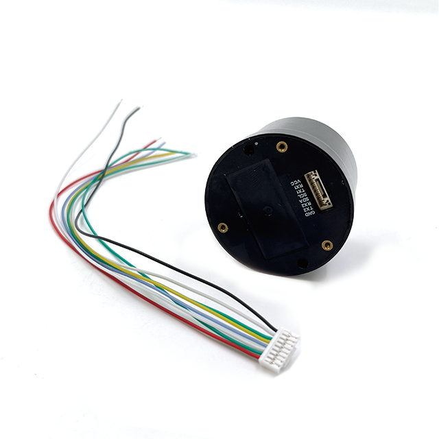
Integrated Ground Plane: A high-performance antenna requires a well-defined ground plane, which acts as a reflector to shape the radiation pattern upwards towards the sky. In compact designs, this is often a printed circuit board (PCB) that also houses the first stage of the low-noise amplifier (LNA). The size and shape of this ground plane are critical for maintaining a good voltage standing wave ratio (VSWR) and a stable phase center.
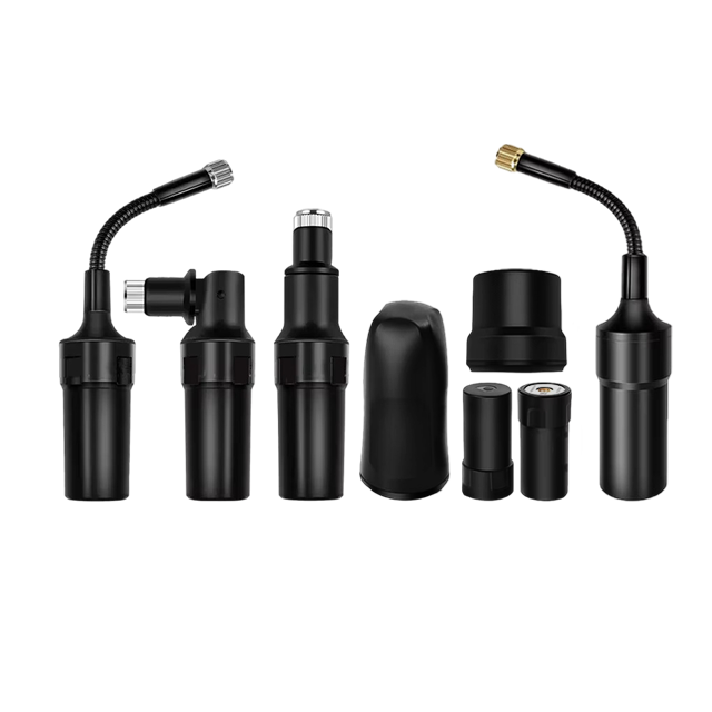
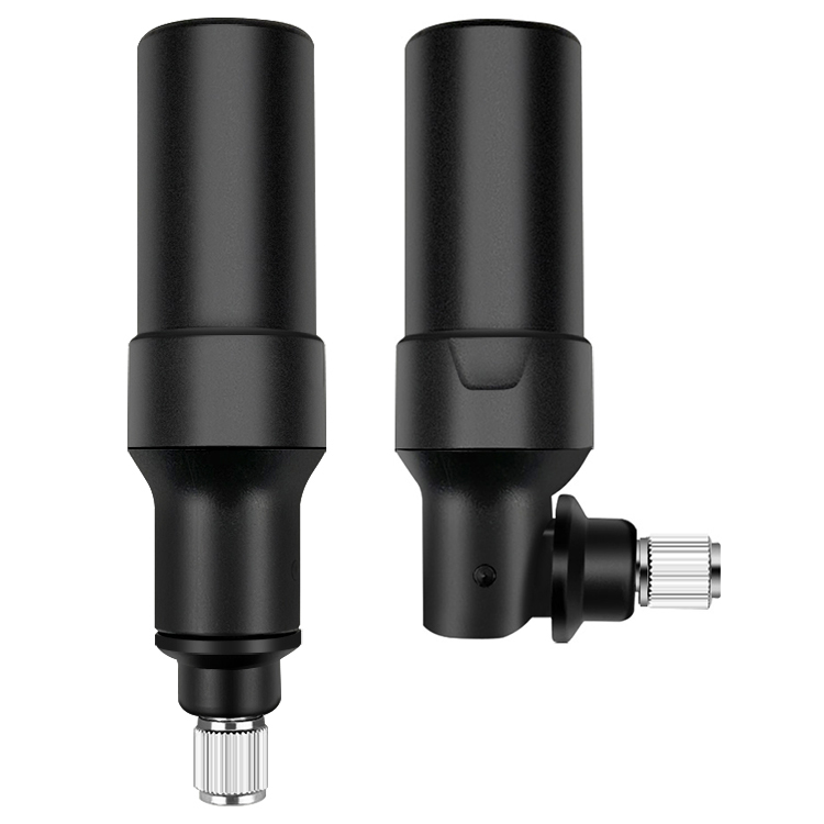
The Complete Assembly: More Than Just a Helix:
A commercial compact helical antenna is a sophisticated system-in-a-package (SiP):
The Radiator: The dielectric-loaded helix itself.
Low-Noise Amplifier (LNA): This is absolutely essential. The satellite signals are incredibly weak (often below -130 dBm). The LNA's primary job is to amplify these signals without adding significant noise (it must have a very low Noise Figure, typically <1.5 dB). It is mounted directly at the feed point of the helix to avoid losses in a cable that would degrade the signal-to-noise ratio before amplification.
Bandpass Filters: Integrated filters are used to reject out-of-band interference from cellular networks (e.g., 4G/5G), Wi-Fi, and other RF sources that could saturate the sensitive receiver.
Power Supply and Conditioning: The antenna is typically powered via the coaxial cable that carries the signal to the receiver (phantom power, often 3-5V DC). Voltage regulators and conditioning circuits on the antenna's PCB ensure clean and stable power for the LNA.
Housing and Radome: The entire assembly is sealed within a rugged, environmentally resistant housing topped with a radome. The radome material is carefully selected to be electromagnetically transparent at GNSS frequencies to avoid detuning the antenna or introducing signal losses. It also provides protection against physical impact, water (IP67 rating is common), and UV radiation.
The construction is a masterpiece of integration, squeezing a highly optimized resonant structure, active electronics, and power systems into a package often no larger than a hockey puck, yet capable of performing a mission-critical function with exceptional reliability.
3.1 Electromagnetic Wave Reception
GNSS satellites transmit electromagnetic waves in the L - band frequency range. When these waves reach the helical antenna, they interact with the helical conductor. The helical shape of the antenna acts as a slow - wave structure. As the electromagnetic wave travels along the helix, the electric and magnetic fields of the wave couple with the electrons in the helical conductor. This interaction causes the electrons to oscillate, generating an electrical current in the conductor.
The helical antenna is designed to be circularly polarized. Circular polarization is beneficial in GNSS applications as it helps in reducing the effects of multipath propagation. Multipath occurs when the satellite signal reaches the antenna via multiple paths, such as direct and reflected paths. A circularly polarized antenna can more effectively distinguish the direct signal from the reflected signals, improving the accuracy of the received signal.
3.2 Phase Center Stability
As mentioned earlier, the phase center of the antenna is crucial for accurate positioning. In a helical antenna, the phase center is determined by the geometry of the helix and the feed system. The stable phase center is achieved through careful design and manufacturing processes. The phase center should remain constant over the operating frequency range and different elevation and azimuth angles. This ensures that the phase differences between the signals received from different satellites are accurately measured, which is essential for calculating the position of the receiver using the triangulation principle.
3.3 Signal Amplification
The signal received by the helical antenna is very weak, typically in the range of - 160 dBm to - 130 dBm. To make this signal usable by the GNSS receiver, it needs to be amplified. A Low - Noise Amplifier (LNA) is integrated into the antenna system. The LNA is designed to amplify the weak signal with minimum noise addition. The noise figure of the LNA is a critical parameter, and high - performance GNSS RTK helical antennas use LNAs with very low noise figures, typically in the range of 1 - 2 dB. The amplified signal is then transmitted to the GNSS receiver through a coaxial cable or other suitable transmission medium.
The compact helical antenna offers a compelling set of advantages that make it the preferred choice for demanding RTK applications, but its design and manufacturing are not without significant challenges and trade-offs.
Advantages:
Superior Multipath Rejection: The inherent RHCP characteristic provides excellent innate rejection of LHCP multipath signals, a primary source of error in urban canyons, near buildings, or in environments with reflective surfaces.
Stable Phase Center: As discussed, the low Phase Center Variation is arguably its greatest advantage for carrier-phase processing. This leads to higher accuracy, more reliable integer ambiguity resolution, and better overall consistency in measurements.
Wide Bandwidth and Multi-Constellation Support: The helical design is inherently a broadband antenna. A single, well-designed helix can efficiently cover all major GNSS bands (L1, L2, L5, E1, E5, B1, B2) without the need for complex feeding networks. This "future-proofs" the antenna against new signals and constellations.
High Gain and Wide Beamwidth: It achieves an optimal balance: high enough gain to boost weak signals and overcome losses, combined with a wide beamwidth to maintain lock on satellites at low elevations. This improves satellite availability and position stability.
Robustness and Durability: The internal structure, often potted with epoxy or other compounds, is highly resistant to vibration, shock, and thermal expansion/contraction. This mechanical stability also contributes to its electrical (phase) stability.
Challenges and Considerations:
Cost and Manufacturing Complexity: This is the primary disadvantage. Manufacturing a precision-wound helix on a dielectric core, integrating it with a high-performance PCB, and assembling it all within a tight tolerance is far more complex and expensive than mass-producing a simple printed patch antenna. The cost of materials, particularly low-loss dielectrics, is also higher.
Size and Form Factor: While "compact" relative to its performance, a helical antenna is still typically taller and sometimes wider than a flat patch antenna. This can make integration into extremely thin devices (like some tablets or phones) challenging, though ongoing miniaturization continues to reduce this gap.
Weight: The dielectric core and more substantial structure generally make it heavier than a patch antenna. For weight-sensitive applications like drones, this is a critical trade-off between performance and flight time.
Calibration Requirement: While its PCV is low, it is not zero. For the highest geodetic-grade accuracy (sub-centimeter), each antenna model must undergo absolute field calibration on a precisely surveyed antenna range to characterize its unique PCO and PCV pattern. This calibration data is then used by processing software to correct measurements. However, this is a standard requirement for all high-precision antennas.
Power Dependency: As an active antenna, it requires a power source. A failure in the power supply or the internal LNA renders the antenna useless, whereas a passive patch antenna would still function (albeit poorly).
In summary, the advantages of the helical antenna are overwhelmingly centered on performance and accuracy, making it the undisputed champion for professional and industrial RTK use. The challenges are primarily economic and related to physical integration, which engineers continually work to overcome.
The unique capabilities of compact GNSS RTK helical antennas have unlocked and enhanced a vast array of applications that demand reliable, centimeter-accurate positioning.
Current Applications:
Precision Agriculture: The quintessential application. Helical antennas are mounted on tractors, harvesters, and sprayers for automated guidance, variable rate application (seeding, fertilizing, pesticides), and yield mapping. Their robustness is key in the harsh vibration environment of farm equipment.
Surveying and Mapping: Used on survey poles, tripods, and base stations. The stable phase center ensures that measurements are consistent and accurate, whether setting a property boundary or conducting a topographic survey.
Unmanned Aerial Vehicles (UAVs) / Drones: This is a massive growth area. Drones for aerial photogrammetry, LiDAR mapping, and agricultural spraying rely on RTK with helical antennas for precise positioning and stable hovering, enabling the creation of highly accurate 2D and 3D models. The antenna's ability to maintain lock during aircraft pitch and roll is critical.
Machine Guidance and Control (Construction, Mining): On bulldozers, graders, and excavators, RTK systems guide blades and buckets to the exact design grade without the need for stakes. The antenna's multipath rejection is vital on chaotic construction sites.
Autonomous Vehicles and Robotics: From research platforms to emerging commercial applications in logistics and last-mile delivery, autonomous systems require a precise and absolutely reliable absolute position as a core sensor input. The helical antenna provides this foundation.
Marine and Hydrographic Survey: Used on boats for precision navigation, channel mapping, and dredging operations.
Future Trends:
Further Miniaturization: The drive will continue to make these antennas smaller, lighter, and lower power for integration into smaller drones, wearable devices, and consumer electronics, potentially bringing RTK-level accuracy to a broader market.
Multi-Frequency, Multi-Constellation as Standard: Future designs will be optimized by default for all available signals (L1, L2, L5, L6, etc.) from all constellations, maximizing accuracy, availability, and reliability through advanced signal combinations.
Tighter Integration with Other Sensors: The antenna will become part of a "Positioning Engine" module that tightly couples the GNSS receiver with inertial measurement units (IMUs), odometry, and potentially even cellular and WiFi positioning in a single, optimized package for seamless navigation in GNSS-denied environments (e.g., tunnels, urban canyons).
Enhanced Interference Mitigation: With the RF spectrum becoming increasingly crowded, future antennas will incorporate more sophisticated integrated filtering and adaptive nulling techniques to combat both intentional and unintentional jamming and interference.
"Smart" or Adaptive Antennas: Research is ongoing into antennas that can electronically steer their beam pattern or adapt their characteristics in real-time to null out interfering signals or to maximize gain towards visible satellites, further enhancing performance in challenging signal environments.
The compact helical antenna is not a static technology; it is evolving to meet the ever-increasing demands of the autonomy and precision positioning revolution.
Conclusion
The compact GNSS RTK helical antenna is a profound example of how a deep understanding of fundamental electromagnetic principles, when combined with advanced materials and precision engineering, can produce a component that is transformative. It is far more than a simple passive element; it is a highly optimized, active electro-mechanical system that serves as the critical first line of defense against error and the primary guarantor of accuracy.
Its innate advantages—exceptional multipath rejection, unparalleled phase center stability, wide bandwidth, and robust gain pattern—make it the superior choice over alternative designs like patch antennas for any application where reliability and centimeter-level precision are non-negotiable. While it carries a cost and size premium, this investment is directly reflected in the quality of the data collected, the efficiency of operations enabled, and the reliability of autonomous systems dependent on it.
As the world moves inexorably towards greater automation in agriculture, construction, transportation, and logistics, the demand for precise and trustworthy positioning will only intensify. The compact helical antenna, continually evolving through miniaturization, broader bandwidth support, and tighter sensor integration, is perfectly positioned to remain the indispensable engine at the heart of the high-precision GNSS ecosystem for the foreseeable future. It is a key enabler, quietly and reliably turning the promise of centimeter-accurate real-time positioning into a practical reality that is reshaping industries and defining the future of automation.

 86 0755 2819 9597
Lucy Yang | lucy.y@toxutech.com
Nicole Li | nicole@toxutech.com
Dotty Zhao | sales04@toxutech.com
Global Business Director / Sales Team / Global Operations


 En
En Cn
Cn Korean
 Home >


