

-
Products -PCBA Manufacturing RF Connectors RF Cable Assemblys Embedded Antennas External Antennas Positioning Chips and Modules
RF Connectors

RF Cable Assemblys
Embedded Antennas
External Antennas
Positioning Chips and Modules


 Language


Language


The evolution of Global Navigation Satellite System (GNSS) technology is a story of simultaneous expansion and contraction. While capabilities have expanded to include multiple constellations (GPS, GLONASS, Galileo, BeiDou, etc.) and frequencies (L1, L2, L5, L6), the form factors of the core components have relentlessly shrunk. At the intersection of this performance and miniaturization trend sits the Compact GNSS RTK Active Antenna, a device that packs the formidable power of centimeter-accurate positioning into a small, lightweight, and highly versatile package.
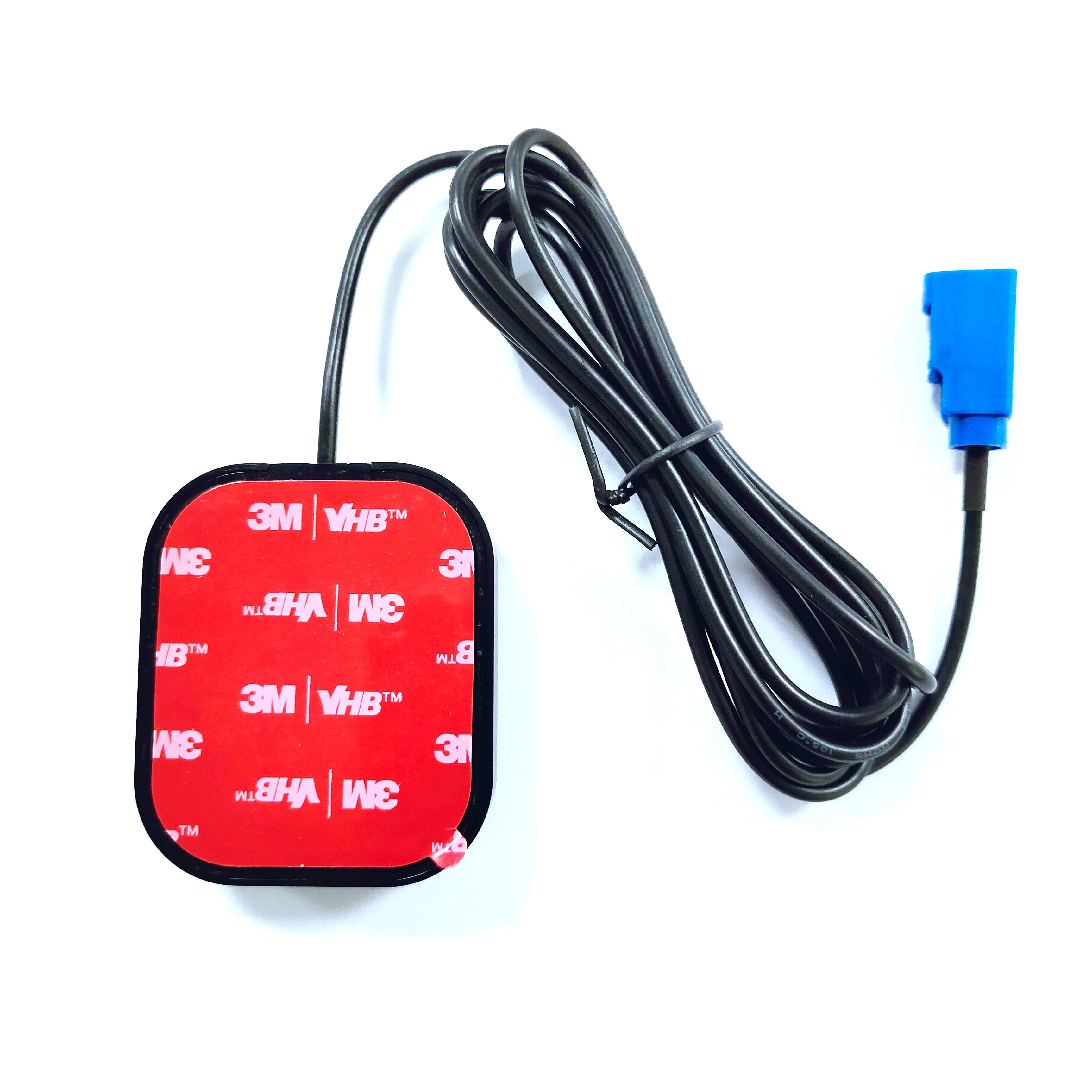
A Compact GNSS RTK Active Antenna is a fully integrated, geodetic-grade antenna and preamplifier system designed for high-precision Real-Time Kinematic (RTK) applications, but with a significantly reduced physical footprint and weight compared to traditional survey-grade antennas. The term "active" denotes the inclusion of a Low-Noise Amplifier (LNA) within the antenna housing, which is essential for boosting the incredibly weak satellite signals before transmission through the cable to the receiver. "Compact" typically refers to antennas with a base diameter of less than 10 cm and a height of a few centimeters, a stark contrast to larger geodetic antennas that often feature wide choke rings and can be over 30 cm in diameter.
This miniaturization is not merely a cosmetic or convenience exercise; it is a critical enabler for a new generation of applications. The large, heavy antennas that defined the early days of high-precision GNSS were perfectly suited for static surveying on a tripod or permanent installation on a building or vehicle roof. However, they are entirely impractical for emerging platforms like small unmanned aerial vehicles (UAVs or drones), handheld mapping devices, wearable technology, robotics, and even consumer applications where size, weight, and aesthetics are paramount constraints.
The core challenge in designing a compact RTK antenna is the fundamental physics of antenna design. Key performance parameters, such as gain pattern, phase center stability, and multipath rejection, are inherently linked to the antenna's physical size. A traditional choke ring, the gold standard for multipath mitigation, is mechanically large because its dimensions are based on the wavelength of the satellite signals it is designed to reject. Therefore, engineers of compact antennas must employ ingenious alternative strategies to achieve high performance within a small volume. This involves advanced materials science, sophisticated electromagnetic modeling, and innovative architectural designs like metamaterials and artificial magnetic conductors to mimic the performance of larger structures.
Despite their small size, these antennas are expected to deliver performance that meets the rigorous demands of RTK processing. They must receive signals from all major constellations across multiple frequencies, provide stable phase center characteristics, offer strong rejection of reflected (multipath) signals, and introduce minimal electronic noise. The integration of the LNA is particularly crucial; it must be a masterpiece of miniaturized, low-noise electronics to ensure that the amplified signal delivered to the receiver is as pure and strong as possible, compensating for any inherent performance trade-offs necessitated by the small radiating element.
In summary, the Compact GNSS RTK Active Antenna is a testament to modern engineering's ability to defy traditional design trade-offs. It represents a paradigm shift from precision as a stationary, bulky tool to precision as a mobile, integrated, and ubiquitous capability. By dissolving the physical barriers to high-accuracy positioning, it opens the floodgates for innovation across countless industries, making centimeter-accurate GNSS an accessible feature on any platform, anywhere.
The design and construction of a Compact GNSS RTK Active Antenna is a complex ballet of electrical engineering, materials science, and mechanical design, all constrained by a fiercely limited volume. Every cubic millimeter must be optimized for performance, making the architecture far more sophisticated than a simple scaled-down version of a larger antenna.
1. The Radiating Element: Multilayer and Multi-Frequency Patches
The heart of the antenna is the radiating element. To achieve multi-frequency operation (e.g., L1, L2, L5) in a small area, designers almost universally abandon single-layer patch designs in favor of stacked or multilayer patches. This involves etching carefully shaped concentric patches onto separate dielectric substrates, which are then laminated together. Each patch and its coupling to the ones above and below are meticulously tuned to resonate at a specific target frequency. This allows a single, compact aperture to generate the necessary radiation patterns for all required GNSS bands simultaneously. The substrates are high-end, low-loss materials like ceramic-filled PTFE (e.g., Rogers RO4350B™) that provide stable electrical properties over temperature and frequency.
2. The Ground Plane: The Miniaturized Guardian
This is the arena where the most innovation occurs. A traditional, large ground plane provides a stable reference and helps define the antenna's radiation pattern. A compact antenna must have a ground plane, but it cannot be large. The solution lies in Engineered or Artificial Ground Planes.
High-Impedance Surfaces (HIS) / Metamaterials: This is a cutting-edge approach. Instead of a solid metal plane, a periodic structure of small metal patches or shapes is etched onto a substrate, separated from a backing metal layer by a thin dielectric. This structure, known as a metasurface, can be designed to act as a magnetic conductor at specific frequencies. For a GNSS antenna, this means it can be designed to suppress surface waves and reject multipath signals arriving at low angles, mimicking the function of a choke ring but in a fraction of the space. The dimensions of the unit cells in this metasurface are smaller than the wavelength, enabling the entire structure to be very compact.
Shorted Annular Rings: Another technique involves placing concentric metal rings around the patch element and shorting them to the ground with vias. These act as band-stop filters, helping to suppress backward radiation and improve the front-to-back ratio, which aids in multipath rejection.
3. The Low-Noise Amplifier (LNA): Miniaturized and Optimized
The LNA in a compact antenna is a marvel of miniaturized RF design. It is no longer a separate module but is often directly integrated onto the same printed circuit board (PCB) that holds the radiating patch or is mounted directly beneath it. Key considerations include:
Ultra-Low Noise Figure: As the first active stage, its noise performance is critical. GaAs or advanced SiGe transistors are used for their superior low-noise characteristics.
Wideband Operation: The LNA must provide flat, high gain across all GNSS frequencies of interest, from ~1150 MHz (GLONASS L3) to ~1610 MHz (BeiDou B1), a significant challenge.
Miniaturized Filtering: Integrated passive devices (IPDs) and surface-acoustic-wave (SAW) or bulk-acoustic-wave (BAW) filters are used immediately after the LNA input to provide strong out-of-band rejection. These components are tiny, allowing for effective filtering without adding significant size.
Power Handling and Protection: A small antenna is more vulnerable to nearby transmitters. Robust protection circuits, using PIN diodes or other limiters, are essential to prevent the LNA from being damaged or desensitized by strong RF fields from cellular, WiFi, or VHF/UHF radios.
4. The Housing and Radome: An Integrated System
The radome on a compact antenna is not just a cover; it is a critical part of the electromagnetic system. Its thickness and dielectric constant are precisely calculated to act as a matching layer, potentially enhancing bandwidth or fine-tuning the antenna's performance. The housing is typically made of high-quality, UV-stable, and often ceramic-loaded plastic that provides mechanical strength and environmental sealing (typically IP67 or higher) without detuning the antenna. The entire assembly is designed to be as low-profile as possible.
5. Phase Center Calibration and Stability
For RTK, the stability of the antenna's phase center—the virtual point from which it measures signal phase—is paramount. In a compact design, the phase center is more susceptible to shift with signal angle (azimuth and elevation) and temperature. Therefore, a massive part of the design process involves rigorous electromagnetic simulation and testing to characterize and minimize these variations. Every compact antenna sold for RTK applications comes with a precise calibration table (an *.pcv or antenna model file) that the RTK processing software uses to correct for these known phase center offsets and variations. Without this model, the antenna could introduce centimeters of error.
In essence, the construction of a compact RTK antenna is a holistic exercise in integration and compensation. Performance that is achieved passively through sheer size in a larger antenna must be achieved actively through clever electromagnetic structures (metamaterials), highly integrated electronics, and sophisticated software correction. It is a tightly coupled system where the boundaries between the radiator, the amplifier, the filter, and the housing are blurred, all working in unison to deliver large-antenna performance from a small-antenna form factor.
The working principles of a Compact GNSS RTK Active Antenna revolve around fulfilling the same core functions as its larger counterparts—signal reception, amplification, and filtration—but doing so within severe physical constraints that require clever workarounds to maintain the signal integrity necessary for carrier-phase-based positioning.
1. The Aperture Challenge and Its Solutions
The most fundamental principle in antenna theory is that performance is related to physical aperture size. A larger antenna can be more directive, have higher gain, and more effectively reject signals from unwanted directions. A compact antenna has a small aperture, which inherently makes it more susceptible to multipath and has a wider beamwidth. Its working principle, therefore, relies on electronic and structural compensation rather than physical dominance.
Multipath Mitigation via Metasurfaces: As described, the metasurface ground plane works on the principle of wave manipulation. It creates a high-impedance surface that reflects incident waves with a zero-degree phase shift (in-phase reflection), unlike a conventional ground plane that causes a 180-degree phase shift. This artificial magnetic conductor effect suppresses the propagation of surface waves that are responsible for exciting the antenna with multipath signals. It effectively makes the small antenna "deaf" to signals coming from near the horizon, which are predominantly reflections.
Maintaining Gain: The integrated LNA provides high gain (often 28-40 dB) to immediately boost the weak signals. This ensures that the signal level is strong enough to dominate the noise floor of the receiver it is connected to, compensating for any slight reduction in passive gain caused by the smaller radiating element.
2. The Signal Chain: Purity in Miniature
The signal path within the antenna is a carefully managed journey:
Reception: The stacked-patch element receives right-hand circularly polarized (RHCP) signals from all visible satellites across multiple frequencies. Its design ensures that the phase center for each frequency is as stable and co-located as possible.
First-Stage Filtering and Protection: Before the LNA, microscopic SAW/BAW filters or integrated passive networks provide initial rejection of very strong out-of-band interference (e.g., cellular signals at 1800 MHz). This prevents the LNA from being overloaded.
Critical Amplification: The LNA performs its primary task: amplifying the faint signals (around -130 dBm) while adding the absolute minimum amount of electronic noise (a low Noise Figure). This step is crucial because any noise added here will be amplified by all subsequent stages in the receiver.
Secondary Filtering and Output: After amplification, further filtering cleans the signal, removing any noise or intermodulation products generated by the LNA itself. The now-strong, clean signal is sent through the output cable to the GNSS receiver. The antenna is typically powered via a DC bias voltage supplied from the receiver through the same coaxial cable (a system called "bias-T").
3. Enabling RTK: The Role of Phase Stability
The entire purpose of the antenna is to provide a stable, low-noise signal for the receiver's carrier-phase tracking loops. The receiver's job is to measure the phase of the carrier wave with millimeter precision. The compact antenna contributes to this by:
Providing a Calibrated Reference: The pre-characterized phase center variation (PCV) model is loaded into the RTK processing software. For every satellite, based on its elevation and azimuth, the software applies a correction to the raw phase measurement to account for the known offset of the antenna's phase center from its mechanical center. This calibration is what allows a small antenna to achieve geodetic-grade accuracy.
Delivering High SNR: The high gain from the LNA ensures a strong signal arrives at the receiver. This allows the receiver's Phase-Locked Loops (PLLs) to run with narrower bandwidths. Narrower loops are more effective at filtering out residual noise (including phase noise), resulting in a "smoother" and more precise phase measurement. This translates directly to lower jitter in the position solution and faster, more reliable integer ambiguity resolution in the RTK engine.
Maintaining Lock: The antenna's ability to reject multipath and interference reduces the rate of cycle slips—momentary losses of lock where the receiver miscounts the number of carrier wavelengths. Fewer cycle slips mean the RTK engine can maintain a fixed solution for longer periods, especially in dynamic or challenging environments.
In principle, the compact active antenna acts as a pre-processor for the GNSS receiver. It takes the chaotic, weak RF energy from the environment, selectively amplifies the desired components, aggressively rejects the undesired ones, and delivers a refined, high-quality signal that gives the receiver's sophisticated digital signal processing algorithms the best possible raw material to work with. It overcomes its physical limitations through a combination of advanced materials, intelligent electromagnetic design, and precise factory calibration.
The adoption of Compact GNSS RTK Active Antennas offers a compelling set of advantages that are driving their rapid proliferation, but these benefits are counterbalanced by a distinct set of challenges inherent to their small size.
Advantages:
Unparalleled Size, Weight, and Power (SWaP) Efficiency: This is the paramount advantage. Their small size and light weight (often 100-300 grams) make them the only viable solution for SWaP-constrained platforms. This includes drones, where every gram directly impacts flight time; robotics; wearable devices; and embedded systems in automotive and consumer electronics where space is at a premium.
Enhanced Versatility and Mounting Options: Their low profile and small footprint allow them to be installed in locations where a traditional antenna would never fit. They can be easily integrated into the chassis of a device, flush-mounted on a vehicle roof without a large hump, or attached to a helmet or backpack for mobile mapping.
Aesthetic and Low-Profile Integration: For applications like autonomous vehicles, advanced driver-assistance systems (ADAS), and consumer products, the visual appearance is important. A compact antenna can be designed to be nearly invisible, integrated seamlessly into the bodywork or housing of a device without being an eyesore.
Cost-Effective Mass Production Potential: While high-end compact antennas are still premium products, their design, which often uses PCB manufacturing techniques and surface-mount components, is inherently more scalable for mass production than large, machined choke ring assemblies. This points towards a future where high-precision GNSS becomes affordable for volume applications.
Reduced Wind Load and Drag: On moving platforms like vehicles, aircraft, and drones, a small antenna presents significantly less wind resistance than a large one, improving energy efficiency and handling.
Challenges and Limitations:
Inherent Performance Trade-Offs: Physics cannot be cheated. A smaller aperture inherently means a wider beamwidth and lower directivity. This can make compact antennas marginally more susceptible to low-elevation multipath and interference from sources near the horizon compared to a large, high-performance geodetic antenna with a deep choke ring. While metasurfaces mitigate this, the performance may not always reach the absolute zenith achievable by the largest antennas.
Thermal Management: Electronic components generate heat. The LNA and other circuits are confined in a very small volume with limited surface area for heat dissipation. Temperature changes can affect the electrical characteristics of the LNA (e.g., gain and noise figure) and the dielectric materials, potentially leading to slight variations in phase center position. High-quality designs must carefully manage this through material selection and thermal design.
Calibration Dependency: The performance of a compact antenna is far more dependent on its unique calibration model (PCV file) than a larger, more symmetric antenna. Using the antenna without the correct and accurate model can introduce significant, systematic errors into the measurements. This ties the user to a specific model and requires software support.
Durability and Exposure: Being small and low-profile, they are often mounted in more exposed locations (e.g., the top of a drone) where they are prone to physical damage, wear, and tear. A large antenna's housing is often its heat sink and protective structure; a compact antenna's housing is thinner and can be more vulnerable.
Cable Loss Considerations: The output signal level is high due to the integrated LNA, but the antenna is still susceptible to cable loss. Using a long or low-quality cable will attenuate the signal and degrade the Signal-to-Noise Ratio (SNR) before it reaches the receiver, negating the benefit of the pre-amplification. Careful selection of low-loss cable is still important.
In conclusion, the advantages of compact antennas are overwhelmingly centered on integration and versatility, unlocking new applications. The challenges are primarily related to the fundamental physics of small antennas and the engineering hurdles of managing heat and ensuring consistent performance. The choice between a compact and a traditional antenna often boils down to the application's priority: ultimate performance in a stationary or benign environment favors larger antennas, while the need for mobility, integration, and versatility makes the compact antenna the undisputed choice.
The Compact GNSS RTK Active Antenna is a key enabling technology, catalyzing innovation across a diverse spectrum of industries by making high-precision positioning available on platforms where it was previously impossible. Its applications are vast and growing, and its evolution is tightly coupled with broader technological trends.
Current Applications:
Unmanned Aerial Vehicles (UAVs / Drones): This is arguably the most significant application. Drones use these antennas for precision agriculture (multispectral mapping, crop spraying), surveying and mapping (photogrammetry, LiDAR), infrastructure inspection, and delivery. The antenna provides the precise geotag for every image or LiDAR point, enabling the creation of highly accurate 2D and 3D models.
Robotics and Autonomous Guided Vehicles (AGVs): Mobile robots in warehouses, factories, farms, and outdoors rely on RTK GNSS for navigation and localization. The compact form factor allows it to be easily integrated onto the robot's body without affecting its balance or design.
Precision Agriculture Machinery: Beyond large tractors, smaller autonomous implements, robotic weeders, and guided sprayers use compact antennas for their size and weight advantages.
Mobile Mapping and GIS Data Collection: Handheld devices, backpack systems, and vehicle-mounted kits for asset management, utility mapping, and GIS data collection use these antennas for their portability and ease of deployment.
Advanced Driver-Assistance Systems (ADAS) and Autonomous Vehicle (AV) Testing: Compact antennas are integrated into production vehicles and test vehicles to provide precise positioning for lane-level navigation, automated parking, and as a source of ground truth for sensor fusion algorithms in AV development.
Marine and Aquatic Applications: Used on small boats, unmanned surface vessels (USVs), and buoys for hydrographic surveying, bathymetry, and oceanographic research.
Future Trends:
Deep Integration into Consumer and IoT Devices: The next logical step is the integration of RTK-level precision into consumer devices. We are already seeing RTK modules in high-end smartphones for improved AR experiences. Future trends could see compact antennas embedded into smart glasses, wearables for fitness and safety, and IoT sensors for logistics and asset tracking.
Tighter Coupling with Inertial and Other Sensors (Sensor Fusion): The future is not standalone GNSS. Compact antennas will be sold as part of tightly integrated GNSS/INS (Inertial Navigation System) modules. The GNSS provides absolute position updates to bound the drift of the miniature IMU (Inertial Measurement Unit), while the IMU provides smooth, high-frequency position and attitude data between GNSS updates and during short signal outages. This fusion is critical for any autonomous system.
Multi-Antenna Systems for Miniaturized Platforms: The use of two or more compact antennas on a single small platform (like a drone) will become common to determine attitude (heading, pitch, roll) with high precision, without relying solely on magnetic compasses which are prone to interference.
On-Chip Integration and "Antenna-in-Package": The ultimate miniaturization will involve integrating the RF front-end, the LNA, and even the radiating element into a single system-in-package (SiP) or module that can be surface-mounted directly onto a device's main PCB. This would make high-precision GNSS as easy to integrate as a WiFi or Bluetooth chip.
Enhanced Robustness and Security: Future designs will focus on making these antennas even more resilient to physical damage, extreme temperatures, and intentional RF interference like jamming and spoofing, which are growing concerns for autonomous systems.
Standardization and Cost Reduction: As volume increases, manufacturing processes will improve, and costs will fall. This will further democratize access to high-precision positioning, moving it from a specialized tool to a standard feature in a vast array of machines and devices.
The compact GNSS RTK active antenna is, therefore, more than just a component; it is a catalyst for the fourth industrial revolution. By providing a precise sense of location to machines, it is a fundamental enabler of the autonomy and data-driven intelligence that will define the future of transportation, agriculture, construction, and countless other fields.
Conclusion
The Compact GNSS RTK Active Antenna represents a pivotal moment in the history of positioning technology. It marks the transition of high-precision GNSS from a specialized tool used by experts in well-defined fields like geomatics and surveying, to a ubiquitous enabling technology that can be embedded into virtually any mobile device or platform. It is the hardware manifestation of the democratization of centimeter-level accuracy.
This democratization is powered by a remarkable feat of engineering. Through the innovative use of metamaterials, multilayer patch designs, and highly integrated electronics, these antennas have successfully decoupled performance from physical size. They have overcome the traditional laws of antenna physics not by breaking them, but by working around them with intelligence and ingenuity. The result is a device that delivers the essential signal integrity required for carrier-phase-based positioning in a form factor that was once thought impossible.
The implications of this are profound. It is no longer a question of if a platform can have high-precision positioning, but why shouldn't it? The barriers of size, weight, cost, and complexity are crumbling. This opens up a new frontier of innovation, allowing engineers and entrepreneurs to re-imagine applications across robotics, autonomy, IoT, and consumer technology with the foundational assumption that their creation can know its location in the world with unparalleled accuracy.
Of course, this shift involves trade-offs. The absolute peak performance of a large, stabilized geodetic antenna may still be necessary for the most demanding scientific applications. However, for the vast majority of dynamic, mobile, and integrated applications, the performance of a modern compact antenna is more than sufficient, and its advantages in versatility and integration are utterly transformative.
In conclusion, the Compact GNSS RTK Active Antenna is far more than a convenient miniaturization. It is a key that unlocks new possibilities. It empowers a future where machines navigate our fields, roads, and cities with precision and awareness; where data about our world is collected with unprecedented geographic fidelity; and where the line between specialized equipment and consumer technology continues to blur. By making precision small, it has made it mighty, seeding the next generation of technological advancement that will be built upon a foundation of knowing exactly where it is.

 86 0755 2819 9597
Lucy Yang | lucy.y@toxutech.com
Nicole Li | nicole@toxutech.com
Dotty Zhao | sales04@toxutech.com
Global Business Director / Sales Team / Global Operations


 En
En Cn
Cn Korean
 Home >


