

-
Products -PCBA Manufacturing RF Connectors RF Cable Assemblys Embedded Antennas External Antennas Positioning Chips and Modules
RF Connectors

RF Cable Assemblys
Embedded Antennas
External Antennas
Positioning Chips and Modules


 Language


Language


In the world of geospatial engineering, where even the smallest deviation can have significant consequences, centimeter-level Real-Time Kinematic (RTK) surveying antennas stand as the gold standard for precision. These specialized antennas are engineered to deliver positional accuracy within 1–2 centimeters horizontally and 2–5 centimeters vertically, a level of precision that transforms industries ranging from land surveying to autonomous construction. Unlike standard RTK systems that may hover around decimeter-level accuracy, centimeter-level RTK antennas are optimized to eliminate even the minutest errors, making them indispensable for applications where exactitude is non-negotiable.
Centimeter-level RTK surveying antennas operate within a closed-loop system that includes a fixed base station and a mobile rover. The base station, positioned at a known coordinate, continuously calculates discrepancies between its actual location and the position derived from satellite signals. These error corrections are transmitted to the rover, which uses its antenna to apply the adjustments in real time. What sets centimeter-level systems apart is their ability to resolve the smallest phase differences in satellite signals, a feat achieved through advanced hardware design and sophisticated signal processing.
The demand for centimeter-level RTK antennas has grown exponentially with the rise of smart infrastructure, precision agriculture, and autonomous systems. These antennas enable tasks such as laying railway tracks with sub-centimeter alignment, mapping floodplains to guide disaster response, and ensuring that solar panels are positioned to maximize energy absorption. As global infrastructure projects become more complex and regulations stricter, the role of centimeter-level RTK antennas in ensuring compliance, safety, and efficiency has never been more critical.
Core Design Features for Centimeter-Level Accuracy
To achieve centimeter-level precision, these antennas incorporate design elements that minimize errors at every stage of signal processing:
Dual-Frequency and Multi-Constellation Support: Centimeter-level RTK antennas are designed to receive signals from multiple GNSS constellations (GPS, GLONASS, Galileo, BeiDou) and at least two frequency bands per constellation (e.g., L1/L2 for GPS). This dual-frequency capability allows the receiver to model and correct ionospheric delays, which are frequency-dependent and can introduce errors of several meters if uncompensated. By combining data from multiple constellations, the antenna ensures a robust satellite lock even in challenging environments, reducing the risk of accuracy degradation due to signal loss.
Ultra-Low Phase Center Variation (PCV): The phase center—the point where satellite signals are electrically processed—must remain stable across all satellite angles and environmental conditions. Centimeter-level antennas achieve PCV as low as 0.5–1 millimeter, a level of stability achieved through precision manufacturing of the radiating element and ground plane. Manufacturers perform rigorous calibration to map PCV across the antenna’s entire field of view, providing correction models that the receiver uses to eliminate residual errors. This calibration is often done in anechoic chambers with robotic positioners to ensure accuracy.
Highly Directional Radiation Patterns with Low Sidelobes: The antenna’s radiation pattern is optimized to focus on satellites while minimizing interference from ground-based reflections. This is achieved through a hemispherical pattern with high gain (8–12 dBi) in the upper hemisphere and suppressed sidelobes, which reduces multipath signals from below. The radiating element is designed to reject signals coming from angles below the horizon, where reflections from buildings, trees, or terrain are most common.
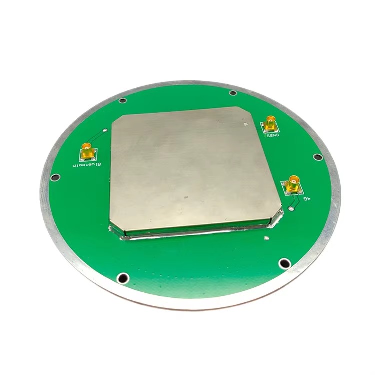
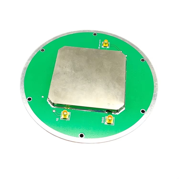
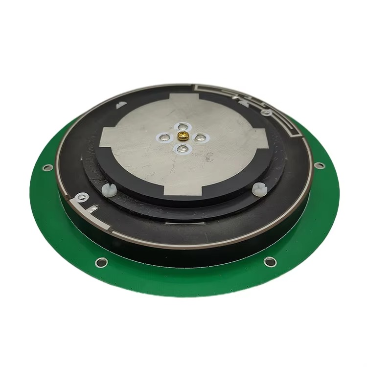
Construction Components
The physical construction of centimeter-level RTK antennas combines advanced materials and precision engineering to maintain performance in harsh field conditions:
Radiating Element: The core signal-capturing component is a multi-layer planar patch array made from high-purity copper or gold-plated copper. These patches are etched onto a low-loss ceramic substrate with a high dielectric constant (εr > 20), allowing for compact design while maintaining high efficiency. The patch geometry is optimized using electromagnetic simulation software to ensure resonance at target frequencies and uniform performance across all supported bands. Each patch in the array is tuned to a specific frequency, with isolation between patches to prevent cross-talk.
Ground Plane: A thick (≥3 mm) aluminum or brass ground plane serves as both a reflective surface and an EMI shield. The ground plane is larger than the radiating element (typically 20–30 cm in diameter) to minimize edge diffraction, which can distort the radiation pattern. For applications requiring minimal weight (e.g., drone mounting), the ground plane may be made from lightweight alloys like aluminum 6061-T6, with reinforcing ribs to maintain rigidity.
Low-Noise Amplifier (LNA) with Advanced Filtering: The LNA is positioned within 1–2 cm of the radiating element to minimize signal loss before amplification. It features a noise figure of <0.8 dB, ensuring that weak signals (as low as -165 dBm) are amplified without introducing significant noise. The LNA is paired with a multi-stage band-pass filter that rejects out-of-band interference from cellular networks (4G/5G), Wi-Fi, and radar systems. Some antennas include a second-stage amplifier near the connector to compensate for cable losses in long runs.
Hermetically Sealed Enclosure: The antenna is encased in a rugged, weatherproof enclosure with an IP68 rating, ensuring operation in submersion up to 2 meters for 30 minutes. The radome is made from fiberglass-reinforced polypropylene or PEEK, materials chosen for their low dielectric loss at GNSS frequencies (<0.01 at 1.5 GHz) and resistance to UV radiation and chemical corrosion. The enclosure includes a pressure equalization valve to prevent damage from temperature-induced air expansion or contraction.
Low-Loss Cable and Precision Connectors: The antenna is connected to the receiver via a low-loss coaxial cable (e.g., LMR-400 or equivalent) with a attenuation of <4 dB/10m at 1.5 GHz. The cable is jacketed in polyurethane for flexibility and resistance to oil, water, and abrasion. Connectors are precision-machined TNC or SMA types with gold plating to ensure low contact resistance and weatherproof seals (O-rings made from EPDM rubber). Some antennas include a built-in bias tee to power the LNA via the coaxial cable, simplifying installation.
Centimeter-level RTK surveying antennas operate on the principle of precise carrier-phase measurement with real-time error correction, with each component optimized to preserve signal integrity:
Signal Capture and Frequency Separation: The radiating element captures L1 and L2 (or equivalent) signals from multiple GNSS constellations. Each frequency band is filtered and directed to a dedicated channel in the LNA, where the signal is amplified. The dual-frequency design allows the receiver to measure the difference in signal travel time between bands, which is used to calculate ionospheric delay correction.
Carrier-Phase Tracking: Unlike code-based positioning (which uses the satellite’s pseudorandom code), centimeter-level RTK relies on tracking the phase of the carrier wave itself. The carrier wave has a much shorter wavelength (19 cm for GPS L1) than the code, allowing for finer distance measurements. The antenna’s stable phase center ensures that the phase measurements are consistent across all satellites, a critical factor for resolving integer ambiguities.
Integer Ambiguity Resolution: The key challenge in RTK is resolving the integer number of carrier wavelengths between the satellite and receiver (integer ambiguity). Centimeter-level systems use dual-frequency data to narrow down the possible ambiguity values, a process accelerated by the antenna’s high SNR. Once resolved, the ambiguities are fixed, and the receiver calculates the distance to each satellite with millimeter-level precision. The antenna’s low noise performance is essential for reliable ambiguity resolution, especially in weak signal conditions.
Reception and Application of Base Station Corrections: The base station, equipped with an identical antenna, calculates errors based on its known position and transmits corrections (via radio or cellular) in formats like RTCM 3.3. The rover antenna receives these corrections, which include residual ionospheric, tropospheric, and satellite clock errors. The receiver applies these corrections to its carrier-phase measurements, eliminating most common GNSS errors.
Real-Time Position Calculation: With corrected carrier-phase data from 5+ satellites, the receiver uses trilateration to calculate the rover’s position. Centimeter-level systems update positions at 10–20 Hz, ensuring that dynamic movements (e.g., a moving excavator) are tracked with minimal latency. The antenna’s ability to maintain lock on multiple satellites during movement is critical for continuous high-precision positioning.
Advantages of Centimeter-Level RTK Surveying Antennas
These antennas offer unique benefits that make them irreplaceable in high-precision applications:
Unmatched Precision for Critical Applications: The primary advantage is their ability to deliver 1–2 cm horizontal accuracy, enabling tasks that demand exact measurements. For example, in railway construction, tracks must be aligned within 2 cm to ensure smooth train operation and prevent derailments. In precision agriculture, seed placement within 3 cm of the target ensures optimal crop spacing and yield.
Reduced Post-Processing and Rework: Unlike lower-accuracy systems that require post-processing or repeated measurements, centimeter-level RTK provides reliable data in real time. This reduces field time and eliminates the need for costly rework, a significant benefit in construction or infrastructure projects where delays can incur daily costs of thousands of dollars.
Enhanced Reliability in Challenging Environments: Multi-constellation, dual-frequency design ensures that the antenna maintains lock even in urban canyons, dense forests, or near power lines. This reliability reduces downtime and allows surveys to proceed in conditions where lower-accuracy antennas would fail.
Compliance with Strict Standards: Many industries (e.g., civil engineering, aerospace) have regulatory standards requiring centimeter-level accuracy. These antennas enable compliance with standards such as the Federal Railroad Administration’s (FRA) track alignment specifications or the International Organization for Standardization’s (ISO) geodetic survey standards.
Integration with Advanced Automation: Centimeter-level antennas are essential for autonomous systems, such as self-driving construction vehicles or drone swarms, which require real-time positioning to navigate and perform tasks without human intervention. The high update rate (10–20 Hz) ensures that these systems can react quickly to changes in their environment.
Challenges and Limitations
Despite their capabilities, centimeter-level RTK antennas face significant challenges:
Extreme Sensitivity to Environmental Factors: While designed to resist interference, these antennas are highly sensitive to multipath, which can introduce errors of 1–5 cm in urban or reflective environments. Wet foliage, calm water surfaces, or metal structures can reflect signals, corrupting carrier-phase measurements. Mitigating multipath often requires careful antenna placement (e.g., away from reflective surfaces) or advanced receiver algorithms, adding complexity to fieldwork.
Strict Base Station Requirements: To maintain centimeter accuracy, the base station must be within 5–10 km of the rover—half the range of standard RTK systems. Beyond this distance, atmospheric differences between base and rover degrade correction quality. Network RTK (NRTK) can extend range to 50+ km, but requires dense base station networks and high-quality communication links, which are unavailable in remote areas.
High Cost and Complexity: Centimeter-level antennas cost 2–3 times more than standard RTK antennas, with prices ranging from \(2,000 to \)10,000. This is due to precision manufacturing, rigorous calibration, and advanced components. Additionally, operating these systems requires specialized training to handle calibration, data processing, and troubleshooting, limiting accessibility for small firms.
Power and Size Constraints: The high-performance LNA and multi-layer construction make these antennas larger and more power-hungry than lower-accuracy models. This can be a drawback in applications like backpack-mounted surveying or small drones, where weight and battery life are critical.
Vulnerability to Jamming and Spoofing: Their high sensitivity makes them more susceptible to intentional or unintentional jamming. Even low-power jammers can disrupt signal lock, requiring re-initialization and causing delays. Anti-jamming features (e.g., adaptive filtering) add cost and complexity.
Applications
Centimeter-level RTK surveying antennas are deployed in applications where precision is mission-critical:
Railway and Highway Construction: In railway alignment, these antennas ensure that tracks are laid with sub-centimeter precision, reducing wear on trains and improving safety. For highways, they guide paving machines to maintain exact slopes and elevations, ensuring proper water drainage and compliance with design specifications.
Precision Agriculture and Autonomous Farming: Farmers use these antennas to guide planters, ensuring seeds are spaced exactly 15–30 cm apart for optimal growth. Autonomous tractors equipped with centimeter-level RTK can till, plant, and harvest with minimal overlap, reducing fuel and input costs by 10–20%.
Structural Monitoring: Bridges, dams, and skyscrapers are monitored for tiny movements (1–5 mm per year) using centimeter-level RTK. These measurements detect early signs of structural stress, allowing for timely maintenance. For example, dams are monitored for horizontal and vertical shifts that could indicate impending failure.
Aerospace and Defense: In aerospace, these antennas are used to align aircraft components during manufacturing, ensuring that wings, engines, and avionics are positioned within 2 cm of design specifications. Defense applications include guiding precision weapons systems and mapping terrain for mission planning.
Mining and Quarrying: Mining operations use centimeter-level RTK to guide drills and blasting, ensuring that ore is extracted efficiently while minimizing waste. Draglines and shovels equipped with these antennas can load trucks with sub-centimeter accuracy, reducing spillage and improving productivity.
Future Trends
The evolution of centimeter-level RTK antennas is driven by advances in materials, connectivity, and computing:
AI-Enhanced Multipath Mitigation: Machine learning algorithms will analyze historical and real-time data to identify and filter multipath signals, reducing errors in urban and reflective environments. These algorithms will adapt to local conditions, improving accuracy in previously challenging locations.
Integration with 5G and LEO Satellites: 5G networks will enable faster, more reliable transmission of RTK corrections, extending NRTK coverage to remote areas. Low Earth Orbit (LEO) satellite constellations (e.g., Starlink, Amazon Kuiper) will provide global correction data, reducing dependence on ground-based base stations.
Miniaturization with Metamaterials: Metamaterials—artificial materials with engineered electromagnetic properties—will enable smaller, lighter antennas with the same performance as current models. This will expand their use in drones, wearable devices, and small autonomous systems.
Quantum-Enhanced Sensing: Research into quantum GNSS receivers could eventually lead to antennas that are immune to jamming and spoofing, while providing even higher accuracy. Quantum sensors would measure signal phases with unprecedented precision, potentially pushing accuracy into the millimeter range.
Energy Harvesting: Future antennas may integrate solar or RF energy harvesting to power the LNA, extending battery life in remote applications. This would be particularly valuable for long-term structural monitoring systems.
Conclusion
Centimeter-level RTK surveying antennas represent the pinnacle of precision in geospatial measurement, enabling applications that demand accuracy beyond the capabilities of standard GNSS systems. Their design—optimized for dual-frequency reception, ultra-low phase center variation, and robust signal processing—ensures that satellite signals are converted into actionable data with sub-centimeter precision. From railway alignment to structural monitoring, these antennas underpin critical infrastructure and industrial processes, ensuring safety, efficiency, and compliance with strict standards.
While challenges such as cost, environmental sensitivity, and base station dependence persist, ongoing advancements in AI, materials science, and connectivity are addressing these limitations. As 5G and LEO networks expand, and metamaterials enable miniaturization, centimeter-level RTK antennas will become more accessible and versatile, opening new applications in autonomous systems, precision manufacturing, and environmental monitoring.
In a world where infrastructure projects grow more complex and the demand for precision increases, centimeter-level RTK surveying antennas will remain essential tools. Their ability to transform satellite signals into centimeter-accurate positions not only drives efficiency and innovation but also ensures the safety and reliability of the systems and structures that shape our daily lives. As technology evolves, these antennas will continue to redefine the boundaries of what is possible in geospatial measurement, enabling a future where precision is the norm rather than the exception.

 86 0755 2819 9597
Lucy Yang | lucy.y@toxutech.com
Nicole Li | nicole@toxutech.com
Dotty Zhao | sales04@toxutech.com
Global Business Director / Sales Team / Global Operations


 En
En Cn
Cn Korean
 Home >


