

-
Products -PCBA Manufacturing RF Connectors RF Cable Assemblys Embedded Antennas External Antennas Positioning Chips and Modules
RF Connectors

RF Cable Assemblys
Embedded Antennas
External Antennas
Positioning Chips and Modules


 Language


Language


In the realm of precision positioning technology, the centimeter-level accuracy multi-system Real-Time Kinematic (RTK) antenna has emerged as a transformative innovation, redefining the standards of location precision across industries. Unlike traditional GPS antennas that typically offer meter-level accuracy, RTK-enabled antennas leverage advanced signal processing and multi-constellation compatibility to deliver positioning results within centimeters— a capability that has become indispensable in applications where even the smallest positional error can lead to significant consequences.
To understand the significance of this technology, it is first critical to contextualize RTK itself. RTK is a satellite navigation technique that enhances the precision of position data derived from global navigation satellite systems (GNSS) by using a fixed reference station to correct errors in real time. While early RTK systems relied solely on GPS (Global Positioning System), modern multi-system RTK antennas integrate signals from multiple GNSS constellations, including GLONASS (Russia), Galileo (European Union), BeiDou (China), and QZSS (Japan). This multi-constellation support is not merely an added feature; it addresses a key limitation of single-system RTK: signal availability. In urban canyons, dense forests, or remote regions where GPS signals may be blocked or weakened, accessing signals from other constellations ensures continuous, reliable positioning.
The demand for centimeter-level accuracy has surged in recent years, driven by industries such as precision agriculture, autonomous vehicles, surveying and mapping, and infrastructure inspection. For example, in precision agriculture, farmers use RTK-equipped tractors and drones to plant seeds, apply fertilizers, and harvest crops with sub-meter to centimeter precision—reducing waste, improving yields, and minimizing environmental impact. In autonomous driving, centimeter-level positioning is critical for lane-keeping, obstacle avoidance, and safe navigation in complex urban environments where even a 10-centimeter error could lead to collisions.
A defining feature of the centimeter-level accuracy multi-system RTK antenna is its ability to handle high-volume, high-frequency data transmission while maintaining signal integrity. Unlike standard antennas, which may struggle with interference or signal degradation, RTK antennas are designed to filter out noise, mitigate multipath effects (where signals reflect off surfaces like buildings or trees before reaching the antenna), and synchronize data from multiple satellites in real time. The integration of multi-system support further enhances this resilience: if one constellation’s signals are compromised, the antenna can seamlessly switch to another, ensuring uninterrupted operation.
Another key aspect of these antennas is their compatibility with RTK receivers and data links. Most modern RTK antennas use standardized connectors (such as SMA or TNC) to interface with receivers, and they rely on radio modems or cellular networks to transmit correction data from the reference station to the rover (the moving device, e.g., a drone or tractor). This real-time data exchange is what enables the antenna to adjust its position calculations on the fly, correcting for errors caused by atmospheric delays, satellite clock drift, and receiver noise.
In summary, the centimeter-level accuracy multi-system RTK antenna represents a convergence of three critical technologies: multi-GNSS signal reception, real-time error correction, and high-precision signal processing. Its ability to deliver consistent, reliable centimeter-level positioning across diverse environments has made it a cornerstone of modern precision applications, and its importance will only grow as industries increasingly adopt autonomous and data-driven technologies.
The design and construction of a centimeter-level accuracy multi-system RTK antenna are engineered to prioritize three core objectives: maximizing signal reception across multiple GNSS bands, minimizing signal interference and multipath effects, and ensuring mechanical durability for use in harsh environments. Every component, from the antenna element to the housing, is carefully selected and optimized to meet these goals, as even minor design flaws can compromise the antenna’s ability to deliver centimeter-level accuracy.
2.1 Physical Design
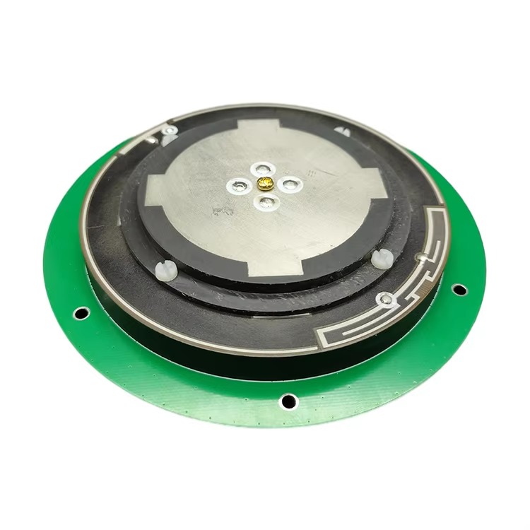
The physical form factor of a multi-system RTK antenna is typically low-profile and compact, though this can vary based on the application. For example, antennas used in drones or handheld surveying devices may be as small as 5–10 cm in diameter, while those installed on agricultural tractors or construction vehicles may be larger (15–25 cm) to accommodate additional signal-enhancing features. Regardless of size, the design is centered around a multi-element array—a key departure from single-element GPS antennas.
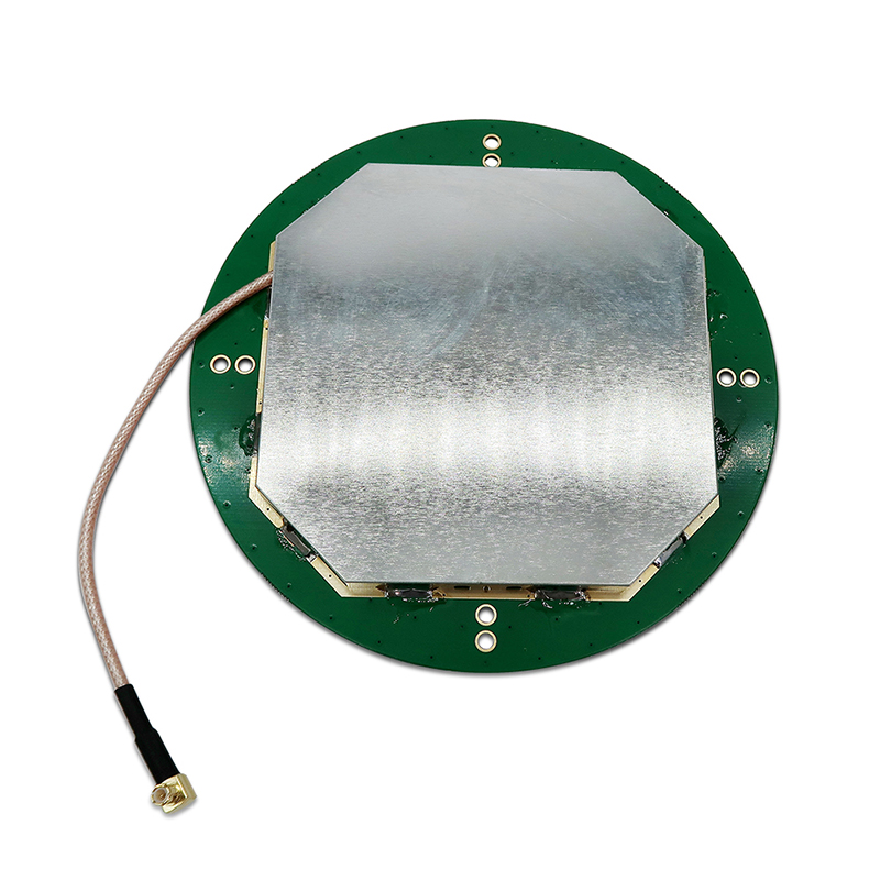
The antenna array consists of multiple conductive elements (usually 4–8) arranged in a circular or hexagonal pattern. Each element is tuned to receive signals from specific GNSS bands, such as GPS L1 (1575.42 MHz), GPS L2 (1227.6 MHz), GLONASS G3 (1202.025 MHz), Galileo E1 (1575.42 MHz), and BeiDou B1 (1561.098 MHz). This multi-element design serves two critical purposes: first, it allows the antenna to simultaneously receive signals from multiple constellations and bands, ensuring redundancy and signal availability. Second, it enables beamforming—a technique where the antenna focuses its reception pattern toward satellites, while reducing sensitivity to signals coming from unwanted directions (e.g., reflected signals that cause multipath errors).
Beneath the antenna array is a ground plane, a flat conductive surface (usually made of aluminum or copper) that acts as a reference for the antenna elements. The ground plane is essential for minimizing signal loss and ensuring consistent radiation patterns. For multi-system RTK antennas, the ground plane is often larger than the antenna array itself (typically 1.5–2 times the diameter of the array) to prevent signals from being absorbed or reflected by the antenna’s mounting surface (e.g., a vehicle roof or drone frame).
Another key physical feature is the radome—a protective cover that encloses the antenna elements and ground plane. The radome is made of a low-dielectric-constant material (such as fiberglass or polycarbonate) to minimize signal attenuation. It is also designed to be weatherproof (IP67 or IP68 rated) to withstand rain, snow, dust, and extreme temperatures. For applications like marine navigation or offshore surveying, the radome may include additional corrosion-resistant coatings to protect against saltwater damage.
2.2 Construction Materials
The choice of materials in a multi-system RTK antenna is dictated by both electrical performance and mechanical durability. Each component is selected to balance these two factors, as materials that excel in signal transmission may be prone to damage, and vice versa.
Antenna Elements: The conductive elements of the antenna are typically made of high-purity copper or copper-clad aluminum. Copper is preferred for its excellent electrical conductivity (99.9% pure copper has a conductivity of 58 MS/m), which ensures efficient signal reception and transmission. However, pure copper is relatively soft and prone to corrosion, so many manufacturers use copper-clad aluminum— a material that combines the conductivity of copper with the lightweight and corrosion resistance of aluminum. The elements are often plated with a thin layer of gold (0.1–0.5 μm) to further enhance conductivity and prevent oxidation, especially in humid or salty environments.
Ground Plane: As mentioned earlier, the ground plane is usually made of aluminum or copper. Aluminum is lighter (density of 2.7 g/cm³ compared to copper’s 8.96 g/cm³) and more cost-effective, making it ideal for portable applications like drones. Copper, however, has higher conductivity and is used in high-performance antennas where signal loss must be minimized (e.g., precision surveying). The ground plane is often bonded to the antenna’s housing using conductive adhesives to ensure a secure electrical connection.
Dielectric Materials: Between the antenna elements and the ground plane, dielectric materials are used to separate the conductive components and control the antenna’s impedance. Common dielectric materials include Teflon (PTFE) and ceramic composites. Teflon is valued for its low dielectric constant (εr ≈ 2.1) and stability over a wide temperature range (-200°C to 260°C), making it suitable for use in extreme environments. Ceramic composites, such as alumina (Al₂O₃) or barium titanate (BaTiO₃), have higher dielectric constants (εr ≈ 9–30) and are used to miniaturize the antenna elements without compromising performance. For example, a ceramic dielectric can reduce the size of an L1-band antenna element by up to 50% compared to a Teflon-based design.
Housing and Radome: The outer housing of the antenna is typically made of reinforced plastic (e.g., ABS or polyamide) or aluminum alloy. Reinforced plastic is lightweight and cost-effective, making it ideal for consumer-grade applications like drones. Aluminum alloy is used in industrial-grade antennas (e.g., construction or marine) for its mechanical strength and resistance to impact. The radome, as noted earlier, is made of fiberglass or polycarbonate. Fiberglass is lightweight and has excellent dielectric properties, while polycarbonate is more impact-resistant—making it suitable for applications where the antenna may be exposed to physical damage (e.g., construction sites).
Connectors: The antenna is connected to the RTK receiver via a coaxial cable with a standardized connector, most commonly SMA (SubMiniature version A) or TNC (Threaded Neill-Concelman). SMA connectors are compact and widely used in consumer and industrial applications, while TNC connectors are more robust and resistant to vibration—making them ideal for automotive or marine use. The connectors are plated with nickel or gold to ensure a reliable electrical connection and prevent corrosion. The coaxial cable itself is designed to minimize signal loss (attenuation) at GNSS frequencies; common types include RG-174 (for short distances) and RG-58 (for longer runs), both of which use a copper inner conductor and a braided copper shield to protect against electromagnetic interference (EMI).
In summary, the design and construction of a centimeter-level accuracy multi-system RTK antenna are a careful balance of electrical performance and mechanical durability. Every component—from the copper antenna elements to the fiberglass radome—is optimized to ensure consistent, reliable centimeter-level positioning across multiple GNSS constellations and harsh environments.
The ability of a centimeter-level accuracy multi-system RTK antenna to deliver precise positioning is rooted in its sophisticated working principles, which combine multi-GNSS signal reception, real-time error correction, and advanced signal processing. Unlike traditional GPS antennas, which simply receive signals and pass them to a receiver, RTK antennas actively collaborate with reference stations and receivers to eliminate errors and refine position data—all in real time. To understand this process, it is essential to break down the working principles into three key stages: signal reception, error correction via RTK, and position calculation.
3.1 Signal Reception: Multi-GNSS Band Capture
The first step in the RTK antenna’s operation is the reception of signals from multiple GNSS constellations. As noted earlier, the antenna’s multi-element array is tuned to capture signals across a range of frequencies used by different constellations. For example, a typical multi-system RTK antenna can receive signals from:
GPS: L1 (1575.42 MHz), L2 (1227.6 MHz), L5 (1176.45 MHz)
GLONASS: G1 (1602 MHz), G2 (1246 MHz), G3 (1202.025 MHz)
Galileo: E1 (1575.42 MHz), E5a (1176.45 MHz), E5b (1207.14 MHz)
BeiDou: B1 (1561.098 MHz), B2 (1207.14 MHz), B3 (1268.52 MHz)
Each antenna element in the array is responsible for capturing signals from a specific set of frequencies. The elements are arranged in a way that maximizes coverage of the sky—ensuring that even if some satellites are blocked (e.g., by a building), the antenna can still receive signals from others. The captured signals are then passed to a low-noise amplifier (LNA)—a critical component that amplifies the weak GNSS signals (which are typically -130 dBm to -150 dBm at the antenna) without introducing additional noise. The LNA is placed as close to the antenna elements as possible to minimize signal loss before amplification— a design choice that is essential for maintaining signal integrity, especially in environments with high EMI.
After amplification, the signals are filtered to remove unwanted frequencies (e.g., cellular or Wi-Fi signals that may interfere with GNSS bands). This filtering is done using band-pass filters that are tuned to each GNSS frequency range. For example, a filter for the GPS L1 band will only allow signals between 1575.42 MHz ± 10 MHz to pass through, blocking all other frequencies. The filtered signals are then converted from analog to digital form using an analog-to-digital converter (ADC)—a process that allows the RTK receiver to process the signals using digital signal processing (DSP) techniques.
3.2 Real-Time Error Correction: The RTK Mechanism
The second, and most critical, stage of the RTK antenna’s operation is real-time error correction. GNSS signals are subject to a range of errors that can degrade positioning accuracy, including:
Atmospheric delays: Signals slow down as they pass through the ionosphere (a layer of charged particles in the upper atmosphere) and troposphere (the lower atmosphere). These delays can cause errors of up to 10 meters in uncorrected GPS positions.
Satellite clock drift: Even the highly precise atomic clocks on GNSS satellites can drift slightly over time, leading to errors in the time-stamp of the signals.
Multipath effects: Signals reflect off surfaces like buildings, trees, or water before reaching the antenna, creating multiple versions of the same signal that arrive at different times. This can cause errors of up to 1–2 meters.
Receiver noise: Electrical noise in the antenna or receiver can distort the signal, leading to small but consistent errors.
RTK addresses these errors by using a reference station—a fixed device with a known, surveyed position that receives the same GNSS signals as the rover (the moving device with the RTK antenna). The reference station calculates the difference between its known position and the position derived from the GNSS signals. This difference, known as the correction vector, contains information about the errors affecting the signals. The reference station then transmits this correction vector to the rover via a data link (e.g., radio modem, cellular network, or satellite).
The RTK antenna plays a key role in this process by ensuring that the rover receives the same signals as the reference station— or as close to the same as possible. Because the antenna is tuned to multiple GNSS bands, it can capture signals from the same satellites that the reference station is using, even if some bands are blocked. The antenna also minimizes multipath effects through its beamforming design, which reduces the reception of reflected signals. This ensures that the errors measured by the reference station are the same as those affecting the rover— a prerequisite for accurate correction.
Once the rover receives the correction vector, it applies it to its own GNSS position calculations. For example, if the reference station measures a 5-meter delay due to ionospheric effects, the rover will subtract 5 meters from its position calculation to correct for this delay. This real-time correction process happens at a rate of 1–10 Hz (1 to 10 times per second), ensuring that the rover’s position is updated continuously as it moves.
3.3 Position Calculation: From Signals to Centimeter-Level Accuracy
The final stage of the RTK antenna’s operation is the calculation of the rover’s precise position. This process, known as trilateration, uses the corrected signals from at least four satellites to determine the rover’s latitude, longitude, and altitude. However, unlike traditional GPS trilateration (which uses uncorrected signals), RTK trilateration leverages the correction vector to eliminate most errors— resulting in centimeter-level accuracy.
Here’s a step-by-step breakdown of the position calculation process:
Satellite Signal Time-Stamp Extraction: The RTK receiver extracts the time-stamp from each received GNSS signal. This time-stamp indicates when the satellite transmitted the signal.
Signal Travel Time Calculation: The receiver calculates the time it took for the signal to travel from the satellite to the rover by subtracting the transmission time from the reception time.
Distance Calculation: The travel time is multiplied by the speed of light (3 x 10⁸ m/s) to calculate the distance (pseudorange) between the satellite and the rover.
Error Correction: The correction vector from the reference station is applied to the pseudorange to eliminate errors caused by atmospheric delays, satellite clock drift, and other factors.
Trilateration: Using the corrected pseudoranges from at least four satellites, the receiver solves a system of equations to determine the rover’s position. For example, if the receiver knows the distance to four satellites and the satellites’ positions (which are included in the GNSS signals), it can calculate the point (latitude, longitude, altitude) that is equidistant to all four satellites— the rover’s precise position.
The multi-system capability of the RTK antenna is critical to this process. By receiving signals from multiple constellations, the antenna ensures that the receiver has access to more satellites than a single-system antenna. This increases the number of pseudoranges available for trilateration, which improves the accuracy and reliability of the position calculation. For example, in an urban environment where GPS signals are blocked by buildings, the antenna may still receive signals from GLONASS or BeiDou satellites— allowing the receiver to maintain centimeter-level accuracy.
In summary, the working principles of a centimeter-level accuracy multi-system RTK antenna are a synergy of multi-GNSS signal reception, real-time error correction, and advanced trilateration. By capturing signals from multiple constellations, amplifying and filtering them to maintain integrity, and collaborating with reference stations to correct errors, the antenna delivers the precise positioning that is essential for
The centimeter-level accuracy multi-system RTK antenna stands out in the field of precision positioning due to its unique set of advantages, but it also faces inherent challenges that limit its widespread adoption in some scenarios. A clear understanding of these pros and cons is essential for industries to make informed decisions about integrating this technology into their operations.
4.1 Advantages
4.1.1 Unmatched Precision
The most prominent advantage of this antenna is its centimeter-level positioning accuracy—a capability that traditional GPS antennas (with meter-level accuracy) cannot match. This precision is a game-changer for industries where even minor positional deviations can have costly or dangerous consequences. In precision agriculture, for instance, centimeter-level accuracy allows farmers to implement “variable-rate technology” (VRT), where seeds, fertilizers, and pesticides are applied only where needed. A study by the International Society of Precision Agriculture found that VRT can reduce fertilizer use by 15–20% while increasing crop yields by 5–10%—a direct result of the RTK antenna’s ability to precisely map field boundaries and soil nutrient variations. In construction, the antenna enables contractors to align structural components (such as steel beams or concrete slabs) with an accuracy of ±2 cm, reducing rework costs and ensuring compliance with strict building codes. For surveyors, this precision eliminates the need for time-consuming ground measurements, cutting project timelines by up to 50% compared to traditional surveying methods.
4.1.2 Multi-Constellation Resilience
Unlike single-system RTK antennas that rely solely on GPS, multi-system RTK antennas can receive signals from multiple GNSS constellations (GPS, GLONASS, Galileo, BeiDou, etc.). This multi-constellation compatibility provides two key benefits: increased signal availability and improved reliability. In urban environments, where tall buildings create “urban canyons” that block GPS signals, the antenna can switch to GLONASS or BeiDou satellites to maintain continuous positioning. For example, a study conducted in downtown Tokyo found that multi-system RTK antennas maintained centimeter-level accuracy 95% of the time, compared to 65% for single-system GPS RTK antennas. In remote regions—such as deserts or polar areas where GPS satellite visibility is limited—access to additional constellations ensures that the antenna can still deliver precise positioning. This resilience is also critical in mission-critical applications like search and rescue, where losing positioning data could put lives at risk.
4.1.3 Real-Time Performance
The “RTK” in the antenna’s name—Real-Time Kinematic—highlights another key advantage: real-time error correction and position updates. Traditional post-processing GNSS systems require users to collect data in the field and then process it later to achieve high accuracy, which delays decision-making. In contrast, multi-system RTK antennas receive correction data from reference stations in real time (at rates of 1–10 Hz), allowing for immediate position adjustments. This is essential for dynamic applications like autonomous vehicles, where the vehicle must react to changing road conditions in real time. For example, an autonomous tractor using an RTK antenna can adjust its path instantaneously to avoid obstacles or follow a precise planting pattern, without waiting for post-processing. In drone surveying, real-time accuracy enables pilots to ensure that the drone covers every part of the survey area without gaps, reducing the need for re-flights.
4.1.4 Adaptability to Harsh Environments
As discussed in the Design and Construction section, multi-system RTK antennas are built with durable materials and weatherproof designs (IP67/IP68 ratings), making them highly adaptable to harsh environmental conditions. They can withstand extreme temperatures (ranging from -40°C to 85°C), heavy rain, snow, dust, and even saltwater corrosion—critical for applications in agriculture (where antennas are exposed to fertilizers and pesticides), marine navigation (saltwater), and construction (dust and debris). For example, RTK antennas used in offshore wind farm inspections are coated with anti-corrosion materials to resist saltwater damage, ensuring reliable performance for up to 10 years. In mining operations, where antennas are exposed to vibrations and heavy machinery, reinforced aluminum housings protect internal components from impact, maintaining accuracy even in rugged conditions.
4.2 Challenges
4.2.1 High Cost of Implementation
One of the biggest barriers to widespread adoption of multi-system RTK antennas is their high upfront and operational costs. The antenna itself is more expensive than traditional GPS antennas—costing anywhere from \(500 to \)5,000, depending on performance and durability. Additionally, implementing an RTK system requires a network of reference stations, which can cost tens of thousands of dollars to install and maintain. For small-scale operations—such as family farms or local surveying companies—these costs can be prohibitive. Even for larger organizations, the cost of upgrading existing equipment (e.g., replacing old GPS receivers with RTK-compatible ones) adds to the financial burden. Operational costs also include data link fees (for transmitting correction data via cellular or satellite networks) and regular maintenance (e.g., calibrating reference stations, replacing worn components). These costs make multi-system RTK antennas less accessible to industries with tight budgets.
4.2.2 Dependence on Reference Station Networks
Multi-system RTK antennas rely on reference station networks to receive correction data—without these networks, the antenna cannot achieve centimeter-level accuracy. While many countries and regions have established public RTK networks (e.g., the U.S. National CORS Network, Europe’s EGNOS, China’s CORS Network), these networks are not available in all areas. In remote regions—such as rural parts of Africa or South America—public reference stations are scarce, forcing users to install their own private reference stations. Installing a private reference station requires purchasing and setting up a fixed GNSS receiver, a communication module (e.g., radio modem), and a power supply—adding significant costs and complexity. Even in areas with public networks, users may face issues with network coverage or latency (delays in correction data transmission), which can degrade accuracy. For example, in areas with poor cellular coverage, transmitting correction data via radio modems may be necessary, but radio signals are limited by line-of-sight and can be blocked by terrain or buildings.
4.2.3 Vulnerability to Electromagnetic Interference (EMI)
Despite their design to filter out noise, multi-system RTK antennas are still vulnerable to electromagnetic interference (EMI)—unwanted electromagnetic signals that can distort GNSS signals. EMI can come from a variety of sources, including power lines, cellular towers, industrial machinery, and even other electronic devices (e.g., smartphones, radios). In industrial environments—such as factories or power plants—high-voltage equipment can generate strong EMI that overwhelms the antenna’s filters, leading to signal loss or reduced accuracy. For example, a study conducted in a steel mill found that EMI from arc furnaces caused the RTK antenna’s accuracy to degrade from ±2 cm to ±10 cm—rendering it unusable for precision tasks. In urban environments, dense cellular networks can cause interference with GNSS bands (e.g., LTE signals operating near the GPS L5 band), leading to “signal jamming” or “spoofing” (where fake GNSS signals are transmitted to trick the antenna). While anti-jamming and anti-spoofing technologies exist, they add to the antenna’s cost and complexity.
4.2.4 Complexity of Installation and Calibration
Installing and calibrating a multi-system RTK antenna is a complex, technical process that requires specialized knowledge. Unlike traditional GPS antennas, which can be simply mounted and connected to a receiver, RTK antennas require precise alignment to ensure optimal signal reception. The antenna must be mounted on a stable, level surface (to avoid tilting, which can affect signal capture) and positioned away from sources of EMI (e.g., metal structures, power cables). Additionally, the antenna must be calibrated to the reference station network— a process that involves inputting the reference station’s coordinates, setting up the data link, and verifying the accuracy of the position output. For users without technical expertise, this process can be time-consuming and error-prone. A single mistake in installation (e.g., mounting the antenna too close to a metal roof) or calibration (e.g., entering the wrong reference station coordinates) can result in significant accuracy errors. Even after installation, regular recalibration is required to account for changes in the environment (e.g., new buildings blocking satellite signals) or wear and tear on the antenna.
5.1 Current Applications
The centimeter-level accuracy multi-system RTK antenna’s unique combination of precision, resilience, and real-time performance has made it indispensable across a wide range of industries. Below are some of its most impactful current applications:
5.1.1 Precision Agriculture
Precision agriculture is one of the largest and fastest-growing markets for multi-system RTK antennas. Farmers use these antennas to optimize every stage of the crop cycle, from planting to harvest. For example:
Precision Planting: RTK-equipped tractors use the antenna’s centimeter-level accuracy to plant seeds in straight rows with consistent spacing (e.g., 20 cm between corn seeds). This ensures that each plant has enough sunlight, water, and nutrients to grow—reducing competition and increasing yields.
Variable-Rate Application (VRA): Drones equipped with RTK antennas fly over fields to map soil nutrient levels, moisture content, and crop health. This data is used to create “application maps” that guide tractors to apply fertilizers, pesticides, and water only where needed. For example, a tractor may apply 50 kg of nitrogen per hectare to a nutrient-poor area and 20 kg per hectare to a nutrient-rich area—reducing waste and environmental impact.
Harvest Optimization: RTK antennas are used in combine harvesters to track the location of harvested crops and map yield variations across the field. This data helps farmers identify areas of the field that are underperforming and adjust their practices for future seasons.
According to a report by MarketsandMarkets, the precision agriculture market is expected to reach $43.4 billion by 2025, with RTK technology accounting for a significant portion of this growth.
5.1.2 Autonomous Vehicles
The development of autonomous vehicles (AVs)—including self-driving cars, trucks, and drones—relies heavily on multi-system RTK antennas. AVs require centimeter-level positioning to navigate safely and accurately, especially in complex environments like urban roads or highways. For example:
Lane-Keeping: Self-driving cars use RTK antennas to maintain their position within a lane (±5 cm accuracy). This is critical for avoiding collisions with other vehicles, pedestrians, and obstacles.
Highway Navigation: Autonomous trucks use RTK antennas to follow precise routes on highways, maintaining a safe distance from other trucks and adjusting speed based on traffic conditions. The real-time accuracy of the antenna ensures that the truck can react quickly to changes in the road (e.g., construction zones, lane closures).
Drone Delivery: Delivery drones use RTK antennas to land precisely on small delivery pads (e.g., on top of buildings or in backyards). The antenna’s multi-constellation support ensures that the drone can navigate safely even in urban environments with tall buildings blocking GPS signals.
Major automotive companies like Tesla, Ford, and Waymo have invested heavily in RTK technology, with some testing self-driving cars equipped with multi-system RTK antennas on public roads.
5.1.3 Surveying and Mapping
Surveying and mapping is one of the oldest and most established applications of RTK technology. Multi-system RTK antennas have revolutionized this industry by reducing the time and cost of surveys while improving accuracy. For example:
Land Surveying: Surveyors use RTK-equipped handheld devices or drones to map property boundaries, topographic features (e.g., hills, rivers), and construction sites. The antenna’s centimeter-level accuracy eliminates the need for traditional “total station” surveys (which require line-of-sight between measurements), allowing surveys to be completed in a fraction of the time.
Geospatial Mapping: Governments and environmental organizations use RTK antennas to create detailed maps of natural resources (e.g., forests, wetlands) and infrastructure (e.g., roads, bridges). These maps are used for urban planning, disaster management, and environmental conservation. For example, after a hurricane, RTK-equipped drones can quickly map flood damage to help emergency responders prioritize rescue efforts.
Mining Surveying: In mining operations, RTK antennas are used to map mine shafts, stockpiles, and haul roads. The antenna’s ability to withstand harsh conditions (dust, vibrations) and deliver real-time accuracy helps miners optimize ore extraction and ensure compliance with safety regulations.
5.1.4 Infrastructure Inspection
Infrastructure inspection—including bridges, tunnels, dams, and wind turbines—requires precise positioning to detect defects (e.g., cracks, corrosion) and monitor structural health over time. Multi-system RTK antennas are used to guide inspection drones and robots, ensuring that every part of the structure is inspected accurately. For example:
Bridge Inspection: Drones equipped with RTK antennas fly along bridges to capture high-resolution images and 3D models. The antenna’s centimeter-level accuracy ensures that the drone follows a consistent path, allowing inspectors to compare images taken over time to detect changes (e.g., new cracks).
Wind Turbine Inspection: RTK antennas are used to guide robots that climb wind turbine blades to inspect for damage. The antenna’s real-time accuracy ensures that the robot stays on course, even in high winds, and captures data from every part of the blade.
Dam Inspection: RTK-equipped underwater drones inspect the foundations of dams for cracks or erosion. The antenna’s multi-constellation support ensures that the drone can navigate accurately even in deep water, where GPS signals are weak.
5.2 Future Trends
As technology advances and industries demand even higher levels of precision and reliability, the multi-system RTK antenna is poised to evolve in several key ways. Below are the most promising future trends:
5.2.1 Integration with 5G and IoT
The integration of multi-system RTK antennas with 5G networks and the Internet of Things (IoT) will unlock new applications and improve performance. 5G networks offer faster data transmission speeds (up to 10 Gbps) and lower latency (less than 1 ms) than traditional cellular networks—critical for real-time RTK applications. For example, 5G will enable RTK antennas to receive correction data from reference stations in near-real time, reducing latency and improving accuracy for high-speed applications like autonomous racing cars. Additionally, integrating RTK antennas with IoT sensors (e.g., temperature, humidity, and motion sensors) will create “smart” positioning systems that can adapt to changing environmental conditions. For example, an IoT-enabled RTK antenna in a greenhouse could adjust its position based on sensor data (e.g., moving to avoid a shaded area) to maintain optimal signal reception. This integration will also enable the development of “precision IoT” applications, such as smart cities, where RTK-equipped IoT devices monitor traffic flow, waste management, and energy use with centimeter-level accuracy.
5.2.2 Miniaturization and Low-Power Design
Advancements in materials science and antenna design will lead to smaller, lighter, and more energy-efficient multi-system RTK antennas. Currently, RTK antennas used in drones and handheld devices are already compact, but future designs will be even smaller—possibly integrated into microchips or wearable devices. For example, researchers at the University of California, Berkeley, are developing “micro-RTK” antennas that are just 1 cm in diameter—small enough to be embedded in smartphones or smartwatches. These miniaturized antennas will enable new applications, such as precision fitness tracking (e.g., tracking the position of a runner’s feet to improve form) or augmented reality (AR) (e.g., overlaying digital information on the real world with centimeter-level alignment). Additionally, low-power designs will extend the battery life of RTK-equipped devices—critical for portable applications like drones (which rely on battery power) or wildlife tracking collars (which need to operate for months without recharging). New materials like graphene (which has high conductivity and low weight) will play a key role in achieving these goals.
5.2.3 Enhanced Anti-Jamming and Anti-Spoofing Capabilities
As the use of GNSS technology grows, so does the risk of jamming and spoofing—malicious attacks that disrupt or falsify GNSS signals. To address this, future multi-system RTK antennas will include advanced anti-jamming and anti-spoofing features. For example, manufacturers are developing “adaptive beamforming” technology that allows the antenna to dynamically adjust its reception pattern to avoid jamming signals. Some antennas will also use machine learning algorithms to detect spoofing attacks (e.g., by comparing GNSS signals to other sensors like accelerometers or gyroscopes) and reject fake signals. Governments and military organizations are already investing in this technology—for example, the U.S. Department of Defense is developing “resilient GNSS” systems that combine RTK with other positioning technologies (e.g., inertial navigation) to ensure positioning even in the event of a jamming attack. In the civilian sector, anti-jamming RTK antennas will be critical for applications like autonomous vehicles and air traffic control, where signal integrity is a matter of life and death.
5.2.4 Expansion of Global Reference Station Networks
To overcome the challenge of limited reference station coverage, governments and private companies are investing in the expansion of global RTK reference station networks. For example, Trimble, a leading GNSS manufacturer, has launched the “Trimble RTK Network”—a global network of reference stations that provides correction data to users via satellite or cellular networks. Similarly, the European Union’s “Galileo High Accuracy Service” (HAS) will provide centimeter-level accuracy across Europe using a network of reference stations. These global networks will make multi-system RTK antennas more accessible to users in remote regions, eliminating the need for private reference stations. Additionally, the use of low Earth orbit (LEO) satellites (e.g., SpaceX’s Starlink) to transmit correction data will further expand coverage, as LEO satellites are closer to Earth and can provide faster, more reliable data transmission than traditional geostationary satellites.
5.2.5 Fusion with Complementary Positioning Technologies
A key future trend for multi-system RTK antennas is the fusion with complementary positioning technologies to create “hybrid positioning systems” that overcome the limitations of standalone GNSS. While RTK delivers exceptional accuracy in open-sky environments, it can struggle in scenarios with full signal blockage (e.g., indoor spaces, underground tunnels, or dense urban canyons). By combining RTK with other technologies—such as inertial navigation systems (INS), LiDAR, computer vision, and ultra-wideband (UWB)—manufacturers can create systems that maintain high accuracy even when GNSS signals are unavailable.
For example, an autonomous vehicle equipped with a hybrid system would use RTK for centimeter-level positioning on highways (where GNSS signals are strong) and switch to INS + LiDAR when entering a tunnel (where GNSS is blocked). INS uses accelerometers and gyroscopes to track the vehicle’s movement based on its initial position, while LiDAR creates a 3D map of the environment to correct INS drift. This fusion ensures that the vehicle maintains ±5 cm accuracy even in signal-free zones. Similarly, in indoor applications like warehouse robotics, RTK antennas can be paired with UWB beacons—small, low-power devices that transmit location signals—to enable centimeter-level positioning inside buildings.
Research institutions are already exploring this trend: the Massachusetts Institute of Technology (MIT) recently developed a hybrid positioning system that combines RTK with computer vision, achieving ±3 cm accuracy in both indoor and outdoor environments. As this technology matures, hybrid RTK systems will expand the antenna’s applications beyond traditional outdoor use cases, opening up new markets like indoor logistics, smart factories, and underground mining.
5.2.6 AI-Driven Signal Optimization
Artificial intelligence (AI) and machine learning (ML) will play an increasingly important role in optimizing the performance of multi-system RTK antennas. Future antennas will integrate AI algorithms to dynamically adjust signal reception, filter noise, and predict potential errors—all in real time. For example, ML models can analyze historical data on satellite signal strength, atmospheric conditions, and EMI sources to predict when signal quality might degrade. The antenna can then proactively adjust its beamforming pattern or switch to a more reliable GNSS constellation to maintain accuracy.
AI will also enhance the antenna’s ability to filter out multipath signals—a major source of error in urban environments. Traditional filters rely on fixed parameters to distinguish between direct and reflected signals, but AI-based filters can learn to recognize the unique characteristics of multipath signals (e.g., delayed arrival times, distorted waveforms) and reject them with greater precision. A study by Stanford University found that AI-powered multipath filtering improved RTK accuracy by 30% in dense urban areas compared to traditional methods.
Additionally, AI will simplify the installation and calibration process for RTK antennas. Currently, calibration requires manual input of reference station coordinates and environmental parameters, but AI-driven systems can automatically detect the antenna’s location, identify nearby EMI sources, and optimize calibration settings. This will reduce the need for specialized technical expertise, making RTK technology more accessible to small-scale users like local farmers or independent surveyors.
Conclusion
The centimeter-level accuracy multi-system RTK antenna has emerged as a cornerstone of modern precision positioning, transforming industries from agriculture to autonomous vehicles by delivering unprecedented levels of accuracy, resilience, and real-time performance. As outlined in this analysis, its core strengths—centimeter-level precision, multi-constellation compatibility, real-time error correction, and durability in harsh environments—address critical needs that traditional GPS antennas cannot meet, enabling innovations that were once considered impractical or impossible.
In precision agriculture, the antenna has enabled the shift from “one-size-fits-all” farming to data-driven, sustainable practices, reducing resource waste and boosting crop yields. In autonomous vehicles, it provides the reliable, high-speed positioning necessary for safe navigation, bringing the vision of fully self-driving cars closer to reality. In surveying and infrastructure inspection, it has streamlined workflows, cut project timelines, and improved the safety of field operations. These applications, among others, highlight the antenna’s role as a catalyst for efficiency, sustainability, and safety across industries.
However, the technology is not without its challenges. High implementation costs, dependence on reference station networks, vulnerability to EMI, and complex installation processes have limited its widespread adoption, particularly among small-scale users and in remote regions. Addressing these barriers will be critical to unlocking the full potential of multi-system RTK antennas—a goal that is being advanced by ongoing trends like the expansion of global reference station networks, miniaturization of hardware, and integration of AI and 5G.
Looking to the future, the evolution of multi-system RTK antennas will be shaped by three key directions: increased integration with emerging technologies (5G, IoT, AI), fusion with complementary positioning systems (INS, LiDAR, UWB), and enhanced accessibility through cost reduction and simplified workflows. These developments will expand the antenna’s reach beyond traditional outdoor applications, enabling new use cases like indoor robotics, smart city management, and underground mining. They will also make centimeter-level positioning more accessible to underserved industries and regions, driving global adoption and innovation.
In summary, the centimeter-level accuracy multi-system RTK antenna is more than just a technical advancement—it is a enabler of a more precise, efficient, and sustainable world. As technology continues to evolve, it will play an increasingly vital role in addressing global challenges, from feeding a growing population (through precision agriculture) to reducing carbon emissions (through optimized transportation and infrastructure). For industries and users alike, embracing this technology will be key to staying competitive in an increasingly data-driven and precision-focused global economy. The journey of multi-system RTK antennas is still in its early stages, and the innovations ahead promise to redefine the limits of what is possible with positioning technology.

 86 0755 2819 9597
Lucy Yang | lucy.y@toxutech.com
Nicole Li | nicole@toxutech.com
Dotty Zhao | sales04@toxutech.com
Global Business Director / Sales Team / Global Operations


 En
En Cn
Cn Korean
 Home >


