

-
Products -PCBA Manufacturing RF Connectors RF Cable Assemblys Embedded Antennas External Antennas Positioning Chips and Modules
RF Connectors

RF Cable Assemblys
Embedded Antennas
External Antennas
Positioning Chips and Modules


 Language


Language


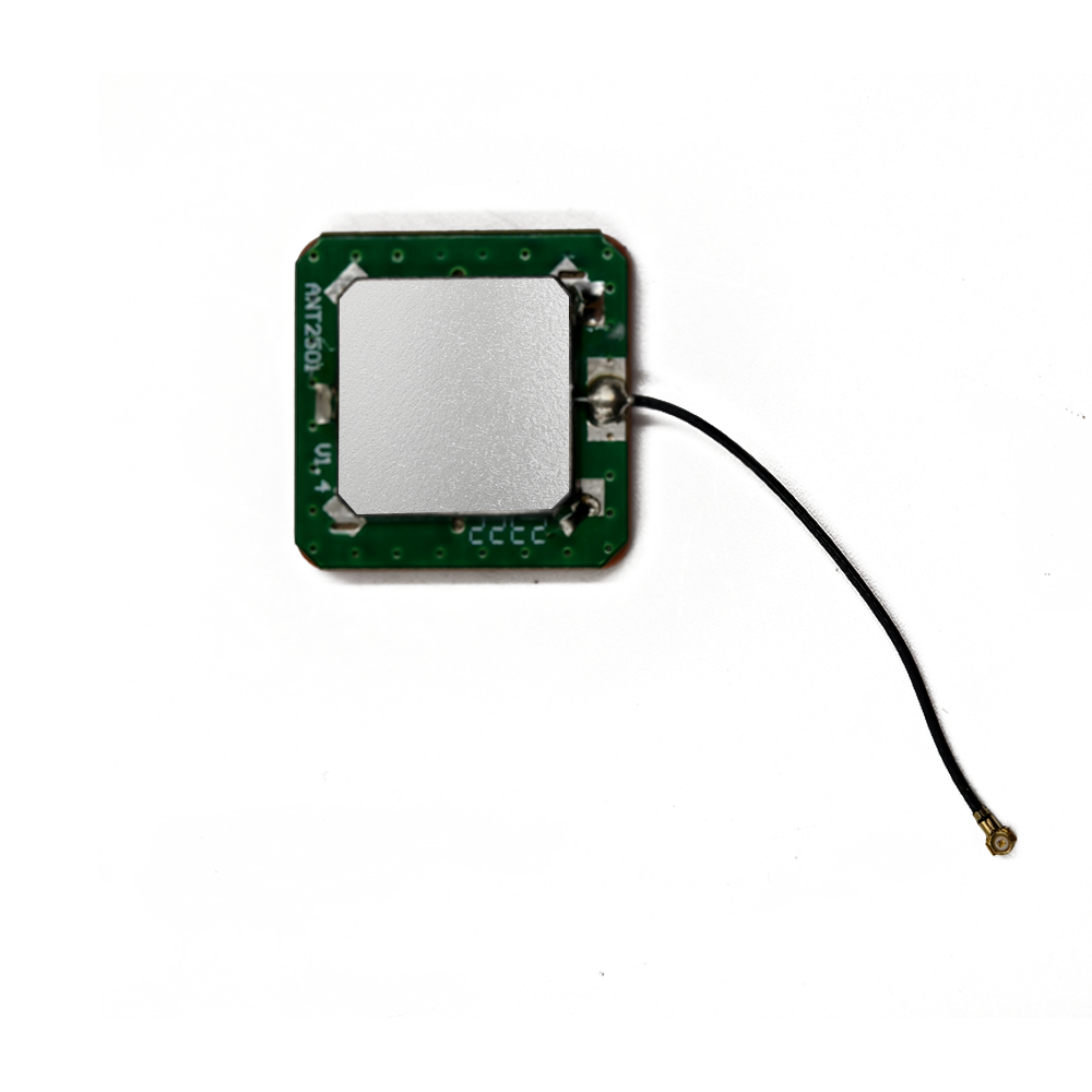
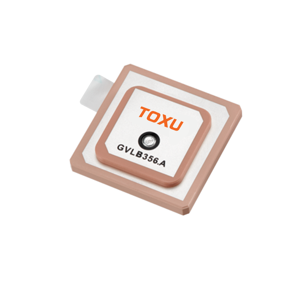

In the realm of compact electronics and integrated navigation systems, the Built-in GPS Ceramic Antenna stands as a testament to engineering efficiency, packing reliable global positioning capabilities into a diminutive form factor. Designed for seamless integration into navigation modules, GNSS receivers, and OEM devices, this antenna leverages the unique properties of ceramic and PCB (FR4) materials to deliver consistent performance in space-constrained environments. From wearable tech to industrial sensors, its features—including IPX connectivity, linear polarity, and a broad frequency range—make it a versatile choice for applications where external antennas are impractical or aesthetically undesirable. This antenna bridges the gap between size and functionality, proving that high-precision positioning need not come at the cost of bulk.
At the heart of the Built-in GPS Ceramic Antenna’s design is its use of ceramic as the primary radiating element, a material chosen for its ability to enable miniaturization without sacrificing performance. Ceramic materials with high dielectric constants (such as alumina or barium titanate) are critical here, as they reduce the wavelength of electromagnetic signals, allowing the antenna to resonate at GPS frequencies (1560-1602 MHz) within a compact 25 x 25 x 4mm footprint. This dielectric property is a game-changer for embedded applications: traditional metal antennas require larger dimensions to achieve resonance at the same frequencies, making them unsuitable for slim devices like smartwatches, drone controllers, or in-dash navigation modules. The ceramic element is precision-engineered to focus signal reception, ensuring that even in its small size, it can capture weak satellite signals. Additionally, ceramic’s stability across temperature fluctuations—from -20°C to +85°C—ensures consistent resonance, a key factor in maintaining positioning accuracy in devices exposed to varying thermal conditions, such as automotive infotainment systems or outdoor sensors.
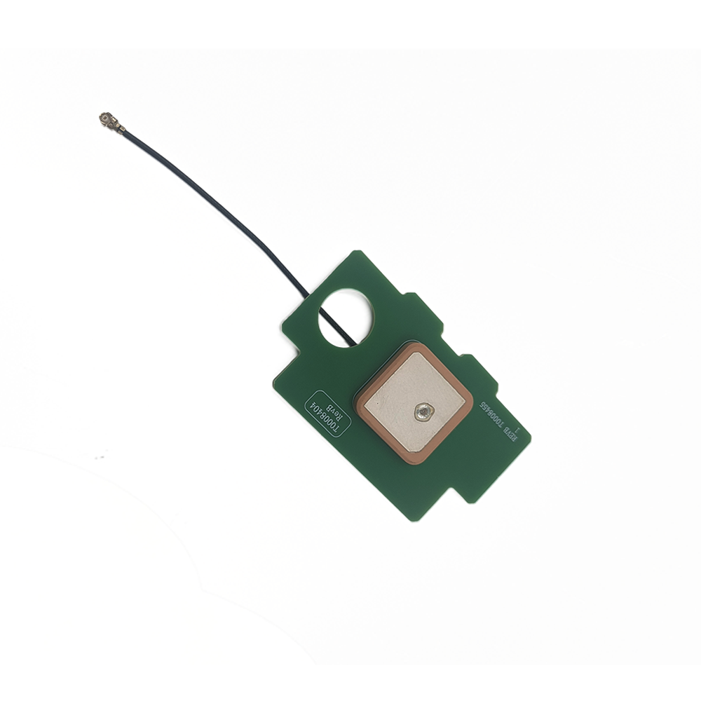
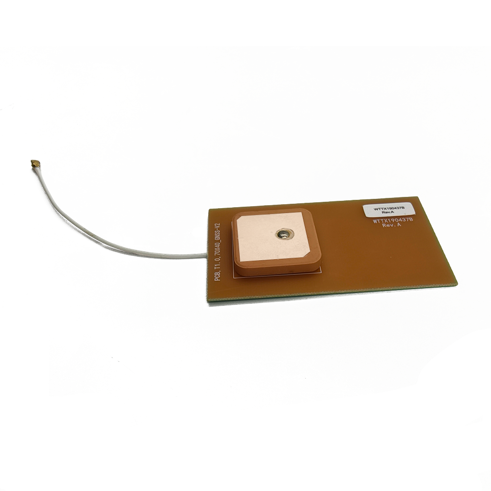
The antenna’s integration with a PCB (FR4) substrate further enhances its suitability for built-in applications, serving both structural and functional roles. FR4, a glass-reinforced epoxy laminate, provides a rigid, thermally stable base for mounting the ceramic radiating element, ensuring precise alignment and mechanical durability. As a ground plane, the PCB helps shape the antenna’s radiation pattern, focusing energy upward toward the sky to maximize satellite signal capture while minimizing interference from surrounding electronics. This is particularly important in densely packed PCBs, where components like processors, memory chips, and power regulators emit electromagnetic noise that could disrupt GPS signals. The FR4 substrate also facilitates easy integration into mass-produced devices, as it can be directly soldered onto the main circuit board during manufacturing, reducing assembly time and costs. For OEMs, this means simplified production workflows and consistent performance across batches, critical for scaling up production of consumer electronics or industrial sensors.
IPX connectivity (also known as U.FL) is a defining feature that underscores the antenna’s focus on miniaturization and integration. Unlike bulkier connectors such as SMA or MCX, IPX connectors are ultra-compact, with a snap-on design that adds minimal height to the antenna assembly—essential for devices where vertical space is limited, such as slim smartphones or fitness trackers. The IPX interface ensures a low-loss connection to the device’s GNSS receiver, with a precision-machined center pin that minimizes signal leakage. While IPX connectors are not as robust as threaded alternatives in high-vibration environments, their integration into fixed PCBs mitigates this risk: in built-in applications, the antenna is protected within the device’s housing, shielding the connector from physical stress. For manufacturers, IPX simplifies automated assembly, as the connectors can be surface-mounted using standard pick-and-place machinery, reducing labor costs and ensuring reliable connections. This compatibility with mass-production processes makes the antenna an attractive choice for OEMs producing high-volume devices, from portable GPS units to IoT sensors.
Linear polarity is a deliberate design choice, optimized for applications where the antenna’s orientation remains fixed relative to satellite signals. Unlike circularly polarized antennas, which counteract polarization rotation caused by the ionosphere, linear polarization aligns the antenna’s electric field along a specific axis (vertical or horizontal). This makes it highly efficient in devices with a consistent orientation, such as dashboard-mounted navigation modules or stationary industrial sensors, where the antenna’s alignment with satellite signals remains stable. In these scenarios, linear polarity minimizes signal loss, ensuring that the antenna captures the maximum possible energy from incoming GPS, BeiDou, or GLONASS signals. While linear polarization is more susceptible to multipath interference—where signals reflect off buildings or terrain and arrive with altered polarization—it is a trade-off that prioritizes simplicity and cost-effectiveness, making the antenna ideal for budget-conscious OEMs. For example, in a fixed-position asset tracker mounted on a shipping container, the antenna’s linear polarity, when aligned vertically, ensures reliable reception of satellite signals passing overhead, maintaining consistent tracking data.
The antenna’s frequency range of 1560-1602 MHz is strategically chosen to cover key civilian GNSS bands, ensuring compatibility with multiple satellite constellations. This range includes GPS L1 (1575.42 MHz), the primary frequency for global positioning, as well as BeiDou B1 (1561.098 MHz) and GLONASS G1 (1602 MHz), expanding coverage in regions where these systems are dominant. This multi-constellation support is critical for reliability: if GPS signals are obstructed by urban canyons or atmospheric interference, the antenna can seamlessly switch to BeiDou or GLONASS, ensuring uninterrupted positioning. For example, in urban China, where BeiDou has strong coverage, the antenna leverages the B1 band to maintain accuracy, while in Russia, GLONASS G1 ensures consistent performance. This versatility eliminates the need for region-specific antenna designs, simplifying inventory management for global OEMs and ensuring that devices work reliably across markets. The broad frequency range also provides a buffer for minor frequency shifts caused by satellite motion or ionospheric activity, ensuring that the antenna remains tuned to the correct signals.
A typical gain of 1.5 dB reflects the antenna’s focus on efficiency in a compact form, balancing signal amplification with the constraints of its small size. While this gain is lower than that of larger external antennas (which may offer 5-10 dB), it is sufficient for built-in applications where the antenna is positioned close to the GNSS receiver, minimizing cable loss. The gain is optimized across the 1560-1602 MHz band, ensuring consistent amplification of signals from GPS, BeiDou, and GLONASS. In practice, this means that even weak signals—such as those penetrating building materials or tree canopies—are amplified enough to be processed by the receiver. For example, in a smartwatch worn by a hiker in a forested area, the antenna’s 1.5 dB gain ensures that satellite signals filtering through the canopy are strong enough to calculate a precise location, supporting features like trail mapping and emergency tracking. The antenna’s gain profile is also designed to avoid amplifying noise, a critical consideration in dense PCBs where electromagnetic interference from other components could corrupt the signal.
VSWR (Voltage Standing Wave Ratio) specifications—2.0 at 1575 MHz and 3.5 at 1602 MHz—provide insight into the antenna’s efficiency in transferring signal power to the receiver. VSWR measures the mismatch between the antenna’s impedance and the 50-ohm standard of most GNSS receivers, with lower values indicating better power transfer. At GPS L1 (1575 MHz), a VSWR of 2.0 ensures that over 90% of the signal power is transferred, minimizing loss and maximizing the signal-to-noise ratio—critical for maintaining accuracy in challenging environments. At GLONASS G1 (1602 MHz), a VSWR of 3.5 is higher, meaning approximately 60% of power is transferred, a compromise made to support multiple bands in a compact design. This trade-off is acceptable because GLONASS often acts as a secondary constellation, supplementing GPS or BeiDou rather than serving as the primary signal source. Manufacturers can further optimize performance by integrating impedance-matching circuits in the receiver, ensuring that even at 1602 MHz, the signal is efficiently processed. For end-users, these VSWR values ensure reliable operation across the antenna’s intended frequency range, with priority given to the most widely used band (GPS L1).
An impedance of 50 ohms aligns the antenna with industry standards for RF systems, ensuring seamless compatibility with GNSS receivers, coaxial cables, and other components in the navigation chain. Impedance matching is critical for maximizing power transfer and minimizing signal reflection, which can cause interference and degrade positioning accuracy. By adhering to the 50-ohm standard, the antenna can be integrated into existing receiver designs without the need for additional matching components, simplifying OEM integration and reducing costs. This compatibility is particularly valuable for manufacturers using off-the-shelf GNSS modules, as it eliminates the need for custom hardware modifications. Whether paired with a budget-friendly receiver in a consumer device or a high-precision chipset in an industrial sensor, the 50-ohm impedance ensures that signal loss is minimized, preserving the integrity of the received data.
The antenna’s compact size—25 x 25 x 4mm—opens up a world of possibilities for integration into space-constrained devices, where every millimeter matters. This miniature form factor fits easily into wearable technology, such as fitness trackers and smartwatches, where it can be embedded in the device’s casing without adding bulk. In drones, it can be integrated into the flight controller, enabling precise positioning for autonomous flight without disrupting aerodynamics. For automotive applications, it fits seamlessly into in-dash navigation systems or ADAS (Advanced Driver-Assistance Systems) modules, where space is occupied by displays, sensors, and control units. The 4mm thickness is particularly noteworthy, allowing the antenna to be embedded in ultra-slim devices like tablet computers or foldable smartphones, where traditional antennas would be too thick. Despite its small size, the antenna’s performance is not compromised: its ceramic radiating element and optimized ground plane ensure that it captures satellite signals with sufficient strength to support accurate positioning.
The RF1.37mm coaxial cable, with a 100mm length, is a critical component in maintaining signal integrity between the antenna and the receiver. RF1.37mm cable is a miniature coaxial variant designed for high-frequency applications, with a small diameter that allows for easy routing within densely packed PCBs. Its construction includes a solid copper center conductor for efficient signal transmission, a dielectric insulator to minimize loss, a braided copper shield to block electromagnetic interference (EMI), and a flexible PVC outer jacket for durability. The braided shield is particularly important in built-in applications, where the antenna is surrounded by noise-generating components like processors and power supplies. By blocking EMI, the shield ensures that the weak GPS signals received by the antenna are not corrupted before reaching the receiver. The 100mm length is optimized for close-range integration: in most embedded systems, the antenna is mounted within centimeters of the receiver, reducing cable loss and ensuring that the signal remains strong. For manufacturers, the pre-attached cable simplifies assembly, as it can be soldered directly to the receiver during production, eliminating the need for manual connector attachment.
The antenna’s operating temperature range of -20°C to +85°C and storage temperature range of -20°C to +65°C ensure reliability in the diverse environments where embedded devices are used. In operating conditions, the ceramic element and PCB substrate remain stable, maintaining their dielectric properties and resonance frequency even as temperatures fluctuate. This is critical for devices like automotive infotainment systems, which are exposed to cabin heat in summer and cold in winter, or outdoor sensors deployed in desert or arctic climates. The IPX connector and RF cable also withstand thermal stress: the cable’s insulation resists hardening in cold temperatures, preventing cracks that could expose the conductor, while the connector’s materials avoid warping in high heat, ensuring a secure connection. During storage, the antenna retains its performance characteristics, with no degradation after extended periods at -20°C to +65°C, a key consideration for OEMs managing inventory or shipping devices across global regions with varying climates.
The antenna’s applications—navigation modules, GNSS receivers, and OEM use—highlight its versatility across industries. In navigation modules, it provides the core positioning data for devices like portable GPS units, ensuring that users receive accurate turn-by-turn directions. Its small size allows these modules to be integrated into rental car systems, hiking gear, or marine equipment, where space is limited. In GNSS receivers, it supports high-precision applications such as surveying, agriculture, and asset tracking, where reliable positioning is critical for operational efficiency. For example, a GNSS receiver mounted on a agricultural drone uses the antenna to map crop health with meter-level accuracy, guiding the drone along precise flight paths. For OEMs, the antenna’s support for OEM/ODM services enables customization, such as tuning the frequency range to regional bands or modifying the cable length to fit specific device layouts. This flexibility makes it a favorite among manufacturers developing proprietary systems, from smart home sensors to industrial IoT devices.
OEM/ODM support is a key advantage that sets the Built-in GPS Ceramic Antenna apart, allowing manufacturers to tailor the antenna to their specific needs. OEM services enable seamless integration into existing product lines, with minimal modifications to the antenna’s design. For example, a smartphone manufacturer can integrate the antenna into their device’s PCB without altering the antenna’s form factor, ensuring compatibility with existing production lines. ODM services, on the other hand, offer more extensive customization: manufacturers can request changes to the ceramic element’s dielectric constant for optimized performance in specific frequency bands, modify the PCB layout to fit unique device casings, or adjust the cable length and connector type for specialized applications. This level of customization is invaluable for niche markets, such as medical devices that require GPS for patient tracking or industrial sensors with unique form factors. By supporting OEM/ODM, the antenna adapts to the diverse needs of the electronics industry, ensuring that it remains a relevant solution for evolving technologies.
In practical use cases, the Built-in GPS Ceramic Antenna excels in scenarios where size and reliability are equally important. In wearable technology, it enables fitness trackers to record precise running routes or hiking trails, even in remote areas with limited satellite visibility. Its small size ensures that the tracker remains lightweight and comfortable to wear, while its ceramic construction withstands sweat and moisture. In drones, the antenna is integrated into the flight controller, supporting features like waypoint navigation and return-to-home functionality. Its linear polarity, when aligned with the drone’s fixed orientation, ensures consistent signal reception during flight, even as the drone pitches and rolls. In automotive applications, it powers in-dash navigation systems, providing real-time location data for traffic updates and route optimization. Its integration into the dashboard ensures that it is protected from the elements, while its IPX connectivity simplifies installation in the vehicle’s electronics suite.
Looking to the future, the Built-in GPS Ceramic Antenna is well-positioned to support emerging technologies in the GNSS space. As satellite constellations expand—with new additions like Galileo and NavIC—the antenna’s broad frequency range (1560-1602 MHz) ensures compatibility with these systems, future-proofing devices for global markets. The rise of IoT (Internet of Things) devices, which rely on compact, low-power components, will further drive demand for miniaturized antennas like this one, as more everyday objects require positioning capabilities. Additionally, advancements in ceramic materials—with even higher dielectric constants—could enable further miniaturization, allowing the antenna to fit into sub-10mm devices like hearing aids or smart tags. For OEMs, the antenna’s adaptability and customization options ensure that it can evolve alongside these technologies, remaining a staple in embedded navigation solutions.
In conclusion, the Built-in GPS Ceramic Antenna represents a masterclass in miniaturized engineering, proving that reliable GPS performance can be achieved in a package small enough for the most compact devices. Its ceramic radiating element, FR4 substrate, and IPX connectivity enable seamless integration into navigation modules, GNSS receivers, and OEM products, while its broad frequency range and linear polarity ensure consistent performance across applications. Whether powering a smartwatch, a drone, or an automotive sensor, this antenna delivers the precision and reliability that manufacturers and end-users demand. As electronics continue to shrink and connectivity becomes more ubiquitous, the Built-in GPS Ceramic Antenna will remain a critical component, enabling the next generation of embedded navigation solutions.

 86 0755 2819 9597
Lucy Yang | lucy.y@toxutech.com
Nicole Li | nicole@toxutech.com
Dotty Zhao | sales04@toxutech.com
Global Business Director / Sales Team / Global Operations


 En
En Cn
Cn Korean
 Home >


