Overview
1.1 Historical Context and Industry Evolution
The adoption of GPS technology in vehicle tracking began in the late 1990s with the U.S. Department of Defense’s decision to make GPS signals freely available for civilian use. Early systems relied on bulky external antennas, such as helical or quadrifilar helix designs, which were impractical for mass-market automotive applications.
The introduction of ceramic patch antennas in the early 2000s revolutionized the industry by enabling:
Miniaturization: Ceramic antennas reduced size by 70–80% compared to traditional designs.
Multi-band Support: Modern antennas now cover GPS L1 (1575.42 MHz), L2 (1227.6 MHz), L5 (1176.45 MHz), and even GLONASS, Galileo, and BeiDou frequencies for global compatibility.
Integration with Telematics: The rise of connected vehicles necessitated antennas that could coexist with 4G/5G, Wi-Fi, and V2X (Vehicle-to-Everything) communication modules.
1.2 Market Drivers and Industry Impact
The global market for built-in GPS ceramic antennas in vehicle tracking is projected to grow at a CAGR of 8.2% from 2023 to 2030, driven by:
Regulatory Mandates: Governments worldwide are enforcing telematics-based insurance (UBI) and fleet safety regulations.
Autonomous Driving: Level 3+ vehicles require centimeter-level accuracy for lane-keeping and collision avoidance.
Commercial Fleet Optimization: Companies use real-time tracking to reduce fuel costs by 15–20% and improve delivery efficiency.
Anti-Theft Systems: GPS tracking reduces vehicle theft recovery times from days to hours.
Key stakeholders include:
OEMs: Automakers like Tesla, Toyota, and BMW integrate antennas into factory-installed telematics units.
Aftermarket Providers: Companies such as Geotab and Verizon Connect offer plug-and-play trackers with ceramic antennas.
Component Suppliers: Leaders like Taoglas, Antenova, and Yokowo dominate the ceramic antenna market with automotive-grade designs.
Design and Construction
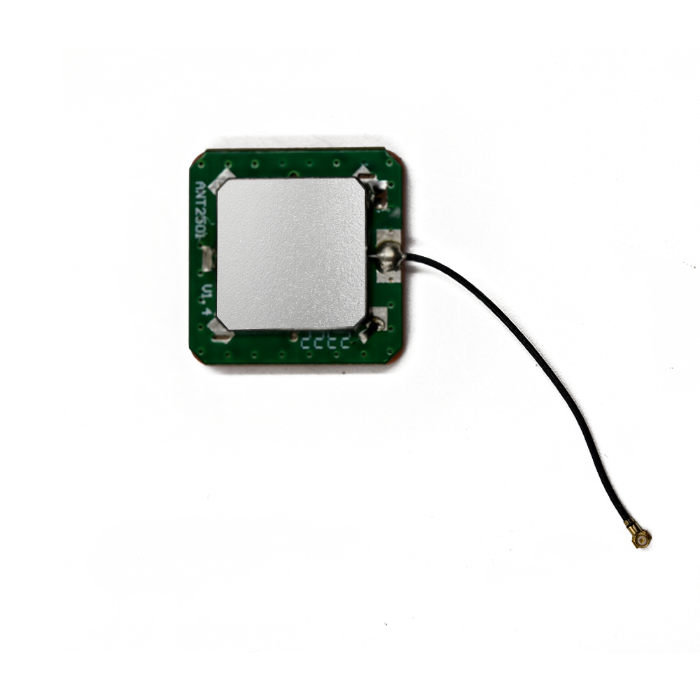
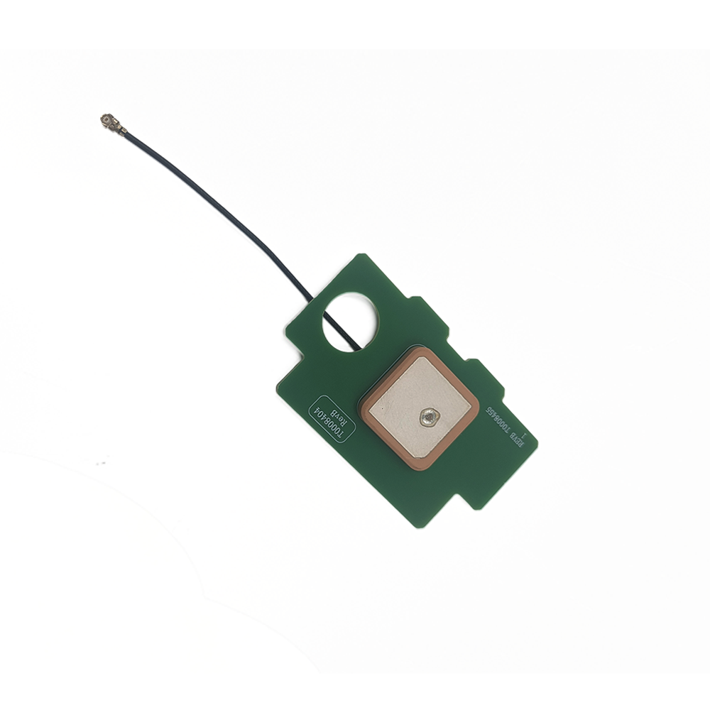
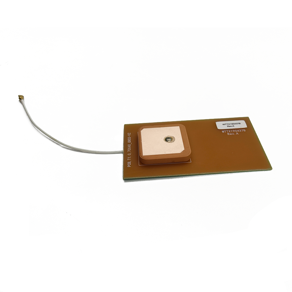
Built-in GPS ceramic antennas for vehicle tracking are engineered to meet stringent automotive standards (e.g., AEC-Q200) while optimizing performance in challenging environments.
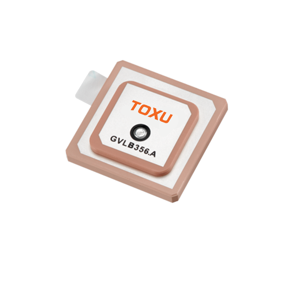
2.1 Core Components and Materials
Ceramic Dielectric Substrate:
Material: High-purity zirconia-titania-alumina (ZTA) composites with dielectric constants (εr) ranging from 9 to 15.
Function: Acts as a resonator to reduce the effective wavelength of GPS signals, enabling compact antenna dimensions.
Example: Kyocera’s AVX-09128A uses a 9.0×9.0×1.2 mm ceramic block with εr = 12.5 for L1/L2 dual-band operation.
Radiating Patch:
Geometry: Typically rectangular or circular, with dimensions optimized for GPS frequencies.
Material: Silver or copper plating (0.5–1 μm thick) for high conductivity.
Tuning: Laser trimming adjusts the patch’s resonant frequency to ±0.5 MHz tolerance.
Ground Plane:
Role: The vehicle’s metal chassis or PCB serves as the ground plane, reflecting signals to form a directional radiation pattern.
Design Consideration: Must maintain a minimum clearance of 10–15 mm from other components to avoid detuning.
Feeding Structure:
Single-Feed: Simplest design, but limited to single-band operation.
Dual-Feed: Enables multi-band support by using two separate feeding points (e.g., L1 and L5).
Active Integration: Some antennas incorporate a low-noise amplifier (LNA) with 20–30 dB gain to boost weak signals in urban canyons.
2.2 Manufacturing Process
Ceramic Sintering:
Ceramic powder is pressed into molds and fired at 1,300–1,500°C to achieve 98%+ density for consistent dielectric properties.
Metallization:
Silver paste is screen-printed onto the ceramic surface and cured at 850°C in a nitrogen atmosphere.
Tuning and Testing:
Network analyzers measure VSWR (Voltage Standing Wave Ratio) and adjust patch dimensions via laser ablation.
Final testing includes:
Gain: ≥2 dBi at zenith.
Axial Ratio: ≤3 dB for circular polarization purity.
Temperature Stability: Performance maintained from -40°C to +85°C.
2.3 Automotive-Grade Enhancements
Environmental Sealing: IP67-rated enclosures protect against dust and water ingress.
Vibration Resistance: Epoxy underfill between the ceramic and PCB prevents cracking during vehicle motion.
EMI Shielding: Ferrite beads and capacitors filter out noise from the vehicle’s 12V/24V electrical system.
Working Principles
Built-in GPS ceramic antennas operate on the principles of electromagnetic resonance and right-hand circular polarization (RHCP) to ensure reliable vehicle tracking.
3.1 Signal Reception Mechanism
Satellite Transmission:
GPS satellites emit L-band signals (L1/L2/L5) with RHCP to minimize multipath interference from buildings and terrain.
Antenna Resonance:
The ceramic substrate’s high εr reduces the signal wavelength, enabling the patch to resonate at the target frequency (e.g., 1575.42 MHz for L1).
Example: A 9×9 mm patch on εr=12.5 ceramic resonates at L1 with a bandwidth of ±2 MHz.
Polarization Matching:
RHCP antennas reject linearly polarized noise (e.g., from FM radio towers) by >20 dB, improving signal-to-noise ratio (SNR).
3.2 Radiation Pattern and Gain
Zenith Gain: Typically 2–3 dBi, optimized for overhead satellite visibility.
Beamwidth: 120° azimuth coverage ensures reception even when the vehicle is parked under trees or bridges.
Multipath Mitigation:
Choke rings around the patch suppress ground reflections.
Advanced designs use spatial diversity by combining signals from multiple antennas (e.g., roof-mounted and dashboard-mounted).
3.3 Impedance Matching
The antenna’s input impedance must match the receiver’s 50 Ω to minimize reflection losses.
Techniques include:
Matching Networks: LC circuits or microstrip lines adjust impedance without physical tuning.
Aperture Coupling: Used in dual-band antennas to isolate L1 and L5 signals.
3.4 Active vs. Passive Antennas
Feature Passive Antenna Active Antenna
Power Requirement None 2.8–5.0 V DC for LNA
Gain 0–2 dBi 20–30 dB (with LNA)
Noise Figure N/A 1.5–2.5 dB
Use Case Open-sky environments (e.g., highways) Urban canyons, tunnels, parking garages
Advantages and Challenges
-
4.1 Advantages
Miniaturization:
Ceramic antennas occupy <10% of the space of traditional helical antennas.
High Performance:
Gain and efficiency (75–85%) outperform PCB antennas in weak-signal scenarios.
Cost-Effectiveness:
Mass production costs are lower than active chip antennas.
Multi-Band Support:
Modern designs cover L1/L2/L5/L6 for high-precision applications.
4.2 Challenges
Design Complexity:
Multi-band antennas require precise tuning and stacking, increasing engineering effort.
Environmental Sensitivity:
Performance varies with PCB layout, enclosure materials, and user hand positioning.
Limited Range:
Passive antennas struggle in deep indoors or dense foliage compared to active alternatives.
Thermal Expansion:
Ceramic and PCB materials expand at different rates, risking detuning over temperature cycles.
Applications and Future Trends
-
5.1 Current Applications
Commercial Fleet Management:
Companies like UPS use GPS trackers to optimize routes and monitor driver behavior.
Consumer Telematics:
Tesla’s Sentinel Mode combines GPS with cameras for anti-theft protection.
Insurance Telematics:
Progressive’s Snapshot® device uses GPS data to offer usage-based insurance discounts.
Emergency Services:
Ambulances and fire trucks rely on GPS for real-time dispatch and navigation.
5.2 Future Trends
5G + GNSS Convergence:
Co-designed antennas will support joint 5G NR and GPS operation for low-latency vehicle communication.
AI-Powered Positioning:
Machine learning algorithms will fuse GPS, IMU, and LiDAR data for autonomous driving in GNSS-denied environments.
Flexible Ceramics:
Printable ceramic inks will enable antennas to conform to curved vehicle surfaces (e.g., dashboards or mirrors).
Quantum GNSS:
Post-quantum cryptography will secure GPS signals against spoofing attacks in critical infrastructure vehicles.
Built-in GPS ceramic antennas have become indispensable for vehicle tracking, offering a unique blend of miniaturization, precision, and cost efficiency. Their evolution from single-band passive components to multi-band active systems reflects the growing demands of connected and autonomous vehicles. While challenges like environmental interference and thermal management persist, ongoing innovations in materials science and sensor fusion promise to overcome these barriers. As the automotive industry transitions toward electric and autonomous mobility, ceramic antennas will remain at the heart of next-generation telematics, ensuring safe, efficient, and reliable vehicle tracking worldwide.
B


 Language
 En
En Cn
Cn Korean

 Home >


 18665803017 (Macro)


