

-
Products -PCBA Manufacturing RF Connectors RF Cable Assemblys Embedded Antennas External Antennas Positioning Chips and Modules
RF Connectors

RF Cable Assemblys
Embedded Antennas
External Antennas
Positioning Chips and Modules


 Language


Language


The relentless march towards miniaturization and integration in technology has profoundly impacted the field of high-precision positioning. While survey-grade pole-mounted antennas with large ground planes represent the pinnacle of performance, a significant class of applications demands a different approach: one that prioritizes compactness, ruggedness, and seamless integration without sacrificing the fundamental benefits of Real-Time Kinematic (RTK) correction. This is the domain of the Built-in GNSS RTK Helical Antenna.
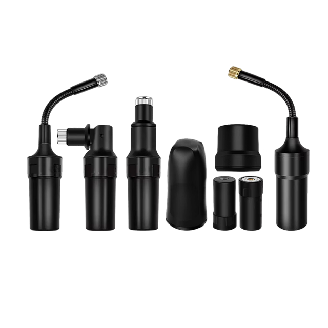
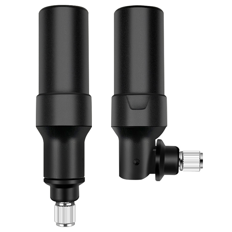
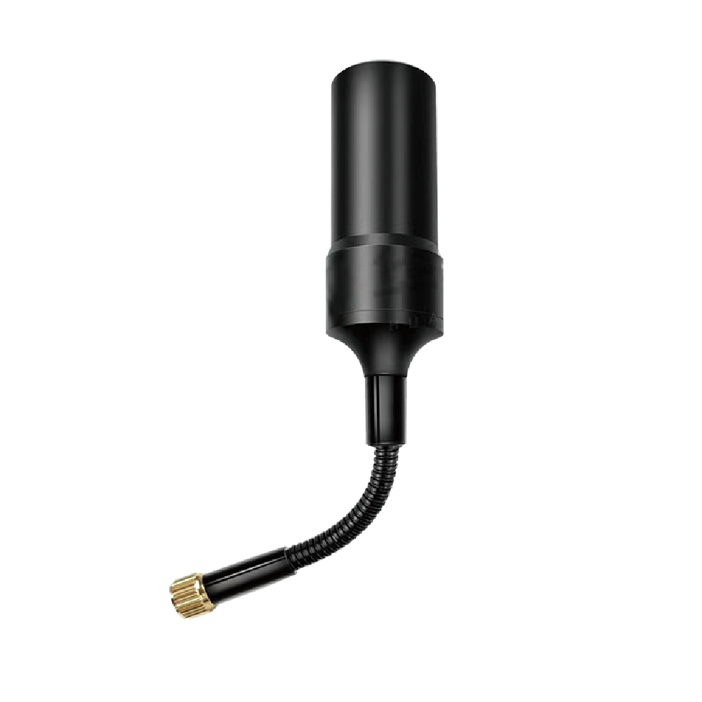
A Built-in GNSS RTK Helical Antenna is a specialized, active antenna designed to be permanently embedded within a device, such as a drone (UAV), a robotic platform, an automotive navigation unit, or a handheld data collector. Its defining characteristic is its form factor—a helix or quadrifilar structure—that allows it to be extremely low-profile while maintaining good performance characteristics essential for RTK and other high-precision GNSS techniques like PPP.
The "Built-in" aspect is crucial. Unlike external antennas that connect via a cable and require separate mounting, this antenna is soldered directly onto a device's main printed circuit board (PCB) or housed in a small, integrated module. This eliminates cable losses, reduces points of failure, simplifies product design, and creates a more robust and aesthetically pleasing end product. However, this integration presents immense engineering challenges, primarily concerning the antenna's interaction with the host device's electronics and its often compromised ground plane.
The "Helical" design refers to its radiating element. Instead of the flat patch found in traditional geodetic antennas, the helical antenna uses a three-dimensional wire or strip wound in a spiral or multiple arms wound into a volumetric structure. This design is chosen for its ability to provide a wide, hemispherical reception pattern and near-hemispherical coverage, which is critical for applications like drones that pitch, roll, and yaw aggressively. A patch antenna, if not perfectly oriented skyward, can suffer from severe signal attenuation. A well-designed helical antenna can maintain a lock on satellites even at low elevations and during dynamic maneuvers.
Despite its small size, this antenna is still "RTK-Grade." This means it is engineered to support the carrier-phase measurements necessary for centimeter-level accuracy. It is a dual-band or multi-band antenna, receiving signals on L1/E1 and L2/E5 frequencies (and sometimes L5) from multiple satellite constellations (GPS, GLONASS, Galileo, BeiDou). This allows it to perform the critical ionospheric error correction that defines advanced GNSS processing. It also contains an integrated Low-Noise Amplifier (LNA) to boost the incredibly weak satellite signals before they are processed by the connected GNSS receiver module.
The primary trade-off between a built-in helical antenna and a large, survey-grade antenna is absolute performance. The helical antenna typically has a higher Phase Center Variation (PCV) and is more susceptible to multipath and interference due to its smaller size and compromised installation environment. However, for its target applications—where size, weight, power (SWaP), and integration are paramount—it represents the optimal compromise, delivering exceptional RTK performance in a package that was once thought impossible.
Designing a Built-in GNSS RTK Helical Antenna is a complex exercise in electromagnetic compromise. Every decision balances performance against the physical constraints of integration, cost, and the electrically "noisy" environment of a modern electronic device.
Radiating Element: The Helix
The core innovation is the helical radiating element. Two main types are prevalent:
Axial Mode Helix: A single wire wound into a spiral cylinder. This design is directional, with the main radiation beam along its axis. It can provide good gain but is more sensitive to orientation.
Quadrifilar Helilar Antenna (QHA): This is the most common and effective design for integrated GNSS applications. It consists of four separate helical arms, often printed on a cylindrical substrate, fed with signals that are 90 degrees out of phase with each other. This creates a truly hemispherical radiation pattern, meaning it can receive signals from satellites in almost any direction above the horizon. This is the "omni-directional" sky coverage essential for dynamic platforms.
The QHA's complex geometry is carefully tuned to resonate at the target GNSS frequencies (e.g., 1575.42 MHz for L1 and 1227.60 MHz for L2). This often involves creating nested or multi-layered structures to achieve dual-band operation within a minimal volume.
The Ground Plane Challenge
This is the single biggest design challenge. In ideal antenna theory, a radiating element requires a large, uninterrupted ground plane to function correctly. It defines the antenna's pattern, gain, and front-to-back ratio. In a built-in application, the antenna must share the device's PCB with processors, memory, radios (Wi-Fi, Bluetooth, Cellular), and power supplies—all of which are sources of noise and interference, and none of which constitute a perfect ground.
Antenna designers use several strategies to mitigate this:
Localized Ground: A dedicated ground plane area is created directly underneath and around the antenna on the PCB. Its size and shape are meticulously optimized through simulation and testing.
Shielding Cans: The antenna and the GNSS receiver section are often housed under a metallic shield to isolate them from noise generated by other components.
Via Fences: Rings of plated-through holes (vias) around the antenna act as barriers, preventing RF energy from leaking into other parts of the board and "tying" different ground layers together to create a more stable reference potential.
Integrated Low-Noise Amplifier (LNA)
The LNA is even more critical in a built-in antenna than in an external one. The satellite signals are not only weak but must now compete with the close-proximity noise generated by the host device. The LNA must provide high gain (e.g., 28 dB) with an exceptionally low noise figure (often < 1 dB). Its placement is strategic—it is located immediately after the radiating element to amplify the desired signal before it has a chance to be degraded by loss in the circuit board traces or overwhelmed by noise.
Filters and Protection
Advanced built-in antennas incorporate Surface Acoustic Wave (SAW) filters or BAW filters between the helix and the LNA. These ultra-precise filters are tuned to the specific GNSS bands and are essential for rejecting powerful out-of-band interference from the device's own cellular modem, Wi-Fi, and other transceivers. Without them, the GNSS front-end would be desensitized or completely jammed. Additionally, protection circuits are included to guard against Electrostatic Discharge (ESD) and voltage spikes from the host device's power supply.
Materials and Fabrication
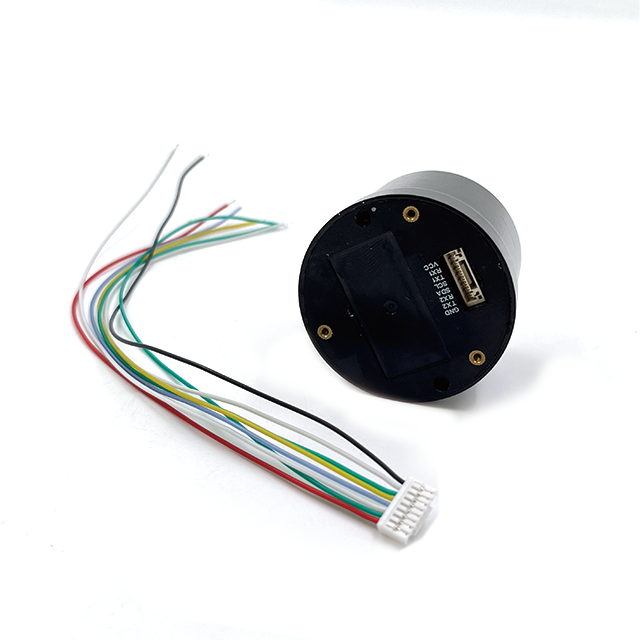
The helix structure is often fabricated using photolithography on a ceramic substrate. Ceramics have a high dielectric constant, which allows the physical size of the antenna to be reduced—a principle known as dielectric loading. The entire assembly—radiating elements, LNA, filters, and matching circuits—is typically packaged into a single, ruggedized Surface-Mount Technology (SMT) module. This module is designed to be automatically picked, placed, and soldered onto the host PCB by standard assembly robots, making it manufacturable at scale.
The entire design process is an iterative loop of 3D electromagnetic simulation (using software like CST or HFSS), prototype fabrication, and rigorous testing in an anechoic chamber to measure its radiation pattern, gain, axial ratio, and phase center stability.
The working principle of a built-in helical antenna shares the same fundamental goal as any RTK antenna: to provide a stable, low-noise, phase-coherent signal for carrier-phase processing. However, achieving this within the hostile environment of a consumer or industrial electronic device requires extraordinary engineering.
Signal Reception in a compromised environment:
The quadrifilar helix excels at receiving signals from a wide range of angles. As RHCP signals from satellites arrive, they induce currents in the four helical arms. The phasing network ensures these signals combine constructively. The critical first step happens instantly: the SAW filter passes the GNSS frequencies (e.g., 1575 MHz ± 10 MHz) while aggressively attenuating everything else, especially the 1.8 GHz, 2.4 GHz, and 3.5 GHz bands used by cellular and Wi-Fi.
Immediate Amplification:
The filtered, femtowatt-level signal is immediately amplified by the integrated LNA. This step is paramount. By amplifying the signal right at the source, the system boosts the desired GNSS signal well above the noise floor that will be introduced by the subsequent PCB trace and the receiver's own circuitry. The LNA's ultra-low noise figure ensures that almost no additional noise is added during this critical amplification stage.
Delivery to the Receiver:
The amplified signal is then passed via a controlled-impedance microstrip trace on the PCB to the GNSS receiver IC. This trace is designed to be as short as possible to minimize loss and is often surrounded by ground planes and guard vias to act as a miniature coaxial cable, preventing radiation and pickup of interference.
The RTK Process with an Integrated Antenna:
The receiver module performs the standard RTK operations: tracking code and carrier phase on L1 and L2 for multiple constellations, receiving correction data from a base station (via a separate radio link, e.g., 4G), and resolving the integer ambiguities.
The unique challenge for the built-in antenna is its Phase Center Stability. The phase center is the electrical point from which the radiation appears to emanate. In a large geodetic antenna, this point is stable and well-calibrated. In a small helical antenna mounted on a noisy PCB, the phase center can shift slightly:
With Frequency: Its location is different for L1 than for L2.
With Angle of Arrival: A signal from directly above may appear to originate from a slightly different point than a signal from the horizon.
With Environment: The proximity of the user's hand, the battery level, or the activity of other components can slightly detune the antenna, causing the phase center to move.
These minuscule shifts introduce errors in the carrier-phase measurement. Therefore, high-quality built-in helical antennas come with a phase center variation (PCV) calibration table. This table maps how the phase center moves relative to a physical reference point on the module. The device's RTK engine must apply these corrections in real-time to achieve its stated accuracy. Without this calibration, the system would be plagued by systematic errors that prevent a stable, high-precision fix.
Multipath Mitigation:
The antenna's hemispherical pattern is a double-edged sword. While great for coverage, it makes the antenna more susceptible to low-elevation multipath signals—reflections from the ground or nearby structures. Sophisticated receiver algorithms are used to weight down low-elevation satellite signals and detect inconsistencies between code and phase measurements to mitigate this multipath.
The adoption of a built-in helical antenna is a deliberate engineering choice driven by a specific set of advantages and a conscious acceptance of its inherent challenges.
Advantages:
Extreme Compactness and Low Profile: The primary advantage. It enables high-precision GNSS functionality in devices where an external antenna is impossible, such as smartphones, compact drones, wearables, and automotive telematics units.
Simplified Integration and Reliability: The SMT module format allows for fully automated assembly, reducing manufacturing cost and improving reliability by eliminating cables, connectors, and their associated points of failure (breakage, moisture ingress, corrosion).
Excellent Hemispherical Coverage: The QHA pattern ensures continuous satellite tracking even on highly dynamic and tilting platforms. A drone performing aggressive maneuvers will not lose lock because the antenna pattern effectively "sees" the entire sky.
Reduced Cable Loss: Since the LNA is integrated, the signal is amplified before being sent to the receiver. This eliminates the several dB of loss typically found in coaxial cables, improving the overall system noise figure.
Aesthetics and Usability: Products can be designed with sleek, uninterrupted form factors without protruding antennas, improving user experience and portability.
Challenges:
Performance Compromise: This is the fundamental trade-off. A built-in antenna will almost always have lower gain, higher phase center variation, and worse multipath rejection than a large, survey-grade antenna with a full ground plane. Its absolute accuracy is typically in the 1-2 cm range under ideal conditions, compared to the sub-centimeter capability of geodetic systems.
Hostile RF Environment: The antenna must operate inches away from powerful noise sources. Despite shielding and filtering, managing this interference is a constant battle and requires careful board layout and system design.
Ground Plane Dependency: Performance is heavily dependent on the PCB layout provided by the device manufacturer. An improperly designed ground plane can render a high-quality antenna module ineffective, leading to poor gain and distorted patterns.
Calibration Intensive: Each antenna design requires individual calibration in an anechoic chamber to characterize its phase center variations across frequency and angle. This calibration data must then be integrated into the device's firmware, adding steps to the manufacturing and software development process.
Thermal Management: The integrated LNA and the host device's components generate heat. Temperature changes can affect the antenna's performance and the LNA's gain, potentially introducing drift that must be managed by the receiver.
Built-in GNSS RTK helical antennas are the enabling technology for a new wave of compact, autonomous, and precision-aware devices.
Applications:
Unmanned Aerial Vehicles (UAVs): The quintessential application. RTK provides the centimeter-level positioning needed for precise corridor mapping, photogrammetry without ground control points, automated infrastructure inspection, and delivery drone landing accuracy. The helical antenna's robustness to motion is critical.
Robotics: Autonomous mobile robots (AMRs) in warehouses, agricultural robots for weeding and harvesting, and last-mile delivery robots all use built-in RTK for precise localization and navigation in outdoor and semi-structured environments.
Advanced Driver-Assistance Systems (ADAS) and Automotive: While not yet used for full autonomy, high-precision GNSS is being integrated for lane-level navigation, validation of sensor data, and intelligent cruise control. The built-in format allows for sleek integration into the vehicle's roof or dashboard.
Precision Agriculture Handhelds and Sensors: Scouts and agronomists use ruggedized tablets with integrated RTK to precisely log weed locations, soil sample points, and crop health data directly into a GIS system.
Consumer Electronics: High-end smartphones and augmented reality (AR) glasses are beginning to incorporate dual-frequency GNSS. While not always used for full RTK, the built-in helical antenna provides the raw data for better accuracy and enables features like precise pedestrian navigation and location-based AR.
Future Trends:
Deeply Integrated "Antenna-on-Chip" (AoC): Research continues into embedding the radiating element directly into the semiconductor package of the GNSS receiver chip itself, further reducing size and cost.
AI-Enhanced RF Management: Future devices will use machine learning to predict and mitigate self-interference. For example, the device could momentarily blank the cellular transmitter during critical GNSS measurements or dynamically adjust the antenna's matching network.
Multi-Antenna Systems (Dead Reckoning): Small devices will incorporate multiple built-in helical antennas. By measuring the phase difference of a satellite's signal across these antennas (a technique called Attitude Determination), the device can not only calculate its position but also its heading without a compass, which is invaluable in urban canyons.
Tighter Coupling with IMUs: The fusion of GNSS and inertial measurement units (IMUs) will become even tighter. The GNSS will provide the absolute position to correct the IMU's drift, while the IMU will provide high-frequency motion data to aid the GNSS receiver in tracking during signal outages, creating a seamless navigation solution.
Standardization of Calibration: As demand grows, calibration processes will become more automated and standardized, making it easier for OEMs to integrate high-precision antennas into their mass-market products.
Conclusion
The Built-in GNSS RTK Helical Antenna is a testament to the incredible progress in RF miniaturization and integration. It represents a paradigm shift from precision as a bulky, external tool to precision as an invisible, embedded feature. It acknowledges that for many transformative applications—from the drone mapping a field to the robot navigating a sidewalk—the perfect should not be the enemy of the good, or more accurately, the exceptional.
It is a masterpiece of compromise, elegantly balancing the unforgiving physics of electromagnetic reception with the harsh realities of commercial product design. While it may not achieve the absolute performance of its larger, geodetic cousins, it delivers a level of accuracy that was unimaginable in such a form factor just a decade ago, thereby democratizing access to centimeter-level positioning.
By solving the profound challenges of noise, size, and phase stability, this technology has become the critical enabler for the next generation of autonomous systems. It is the hidden facilitator that allows machines to understand their place in the world with remarkable precision, paving the way for a future where intelligent devices navigate our environments seamlessly, safely, and efficiently. The built-in helical antenna, though often unseen, is truly a cornerstone of the automated and spatially aware future.

 86 0755 2819 9597
Lucy Yang | lucy.y@toxutech.com
Nicole Li | nicole@toxutech.com
Dotty Zhao | sales04@toxutech.com
Global Business Director / Sales Team / Global Operations


 En
En Cn
Cn Korean
 Home >


