

-
Products -PCBA Manufacturing RF Connectors RF Cable Assemblys Embedded Antennas External Antennas Positioning Chips and Modules
RF Connectors

RF Cable Assemblys
Embedded Antennas
External Antennas
Positioning Chips and Modules


 Language


Language


In the vast expanse of the ocean, accurate navigation is not just a convenience but a necessity for the safety of boats and ships. Boat - mounted marine GNSS (Global Navigation Satellite System) antennas play a pivotal role in this regard. These antennas are designed to receive signals from multiple satellite constellations, such as GPS (Global Positioning System), GLONASS (Globalnaya Navigatsionnaya Sputnikovaya Sistema), Galileo, and BeiDou.
The development of marine GNSS antennas has been a continuous process, evolving with the advancements in satellite technology. In the early days, basic GPS antennas were used for marine navigation, but they had limitations in terms of accuracy and signal reception in challenging environments. As the demand for more precise positioning increased, especially for commercial shipping, fishing fleets, and recreational boating, multi - constellation and multi - frequency GNSS antennas were introduced.
These modern antennas can simultaneously receive signals from different satellite constellations operating at various frequencies. For example, the L1 frequency (around 1575.42 MHz) is commonly used for civilian applications, while the L2 frequency (around 1227.60 MHz) and L5 frequency (around 1176.45 MHz) offer improved accuracy and signal robustness. By leveraging multiple constellations and frequencies, marine GNSS antennas can achieve higher positioning accuracy, often in the sub - meter range for high - end models.
Marine GNSS antennas are also designed to withstand the harsh marine environment. They are typically enclosed in waterproof and weatherproof enclosures, with ratings such as IP66 or IP67, which protect against dust and water ingress. The materials used in their construction are corrosion - resistant, ensuring long - term reliability even when exposed to saltwater, high humidity, and strong winds.
The market for boat - mounted marine GNSS antennas is diverse, with a wide range of products available to suit different applications and budgets. From small, compact antennas for recreational boats to large, high - performance antennas for commercial vessels and military ships, there is a solution for every need. The choice of antenna depends on factors such as the required accuracy, the type of boat, the operating environment, and the cost - effectiveness.
2.1 Antenna Elements
The core of a marine GNSS antenna is its antenna elements. These elements are responsible for receiving the weak satellite signals and converting them into electrical signals that can be processed by the GNSS receiver. There are different types of antenna elements used in marine GNSS antennas, with the most common being patch antennas and helical antennas.
Patch antennas are widely used due to their compact size, low profile, and good performance. They consist of a flat, conductive patch printed on a dielectric substrate. The patch is typically square or circular in shape and is designed to resonate at the frequencies of the GNSS signals. Patch antennas can be arranged in arrays to improve the antenna's gain and directivity. For example, a multi - patch antenna array can provide better signal reception in different directions, which is crucial for marine applications where the satellite visibility may vary.
Helical antennas, on the other hand, are known for their excellent circular polarization characteristics. Circular polarization is important for GNSS antennas as it helps in reducing the effects of multipath interference. Multpath occurs when the satellite signals bounce off surfaces such as the water, boat hull, or nearby structures before reaching the antenna. Helical antennas are wound in a spiral shape around a central axis and can be either right - hand or left - hand polarized. They are often used in combination with patch antennas in high - performance marine GNSS antennas to enhance the overall performance.
2.2 Enclosure and Mounting
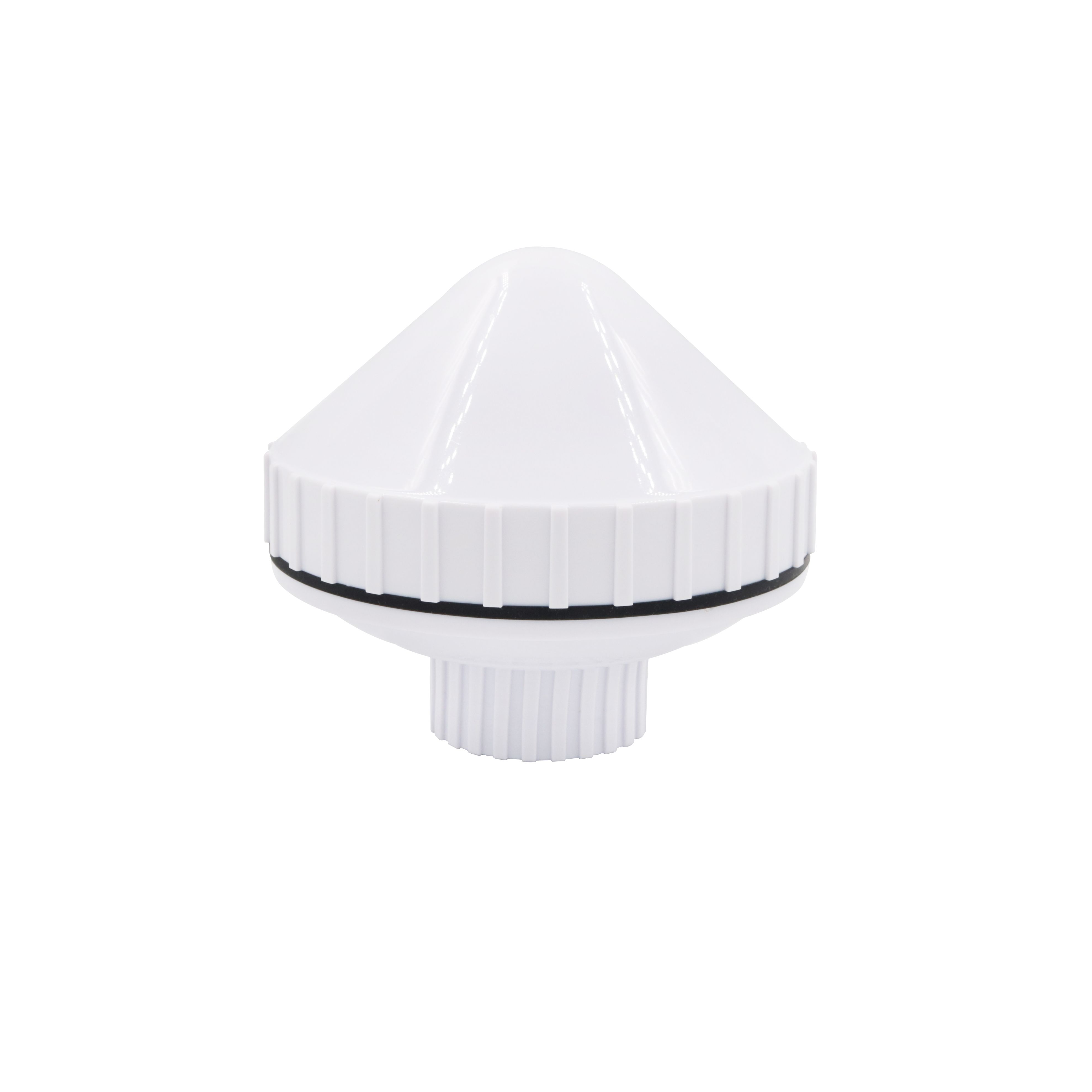
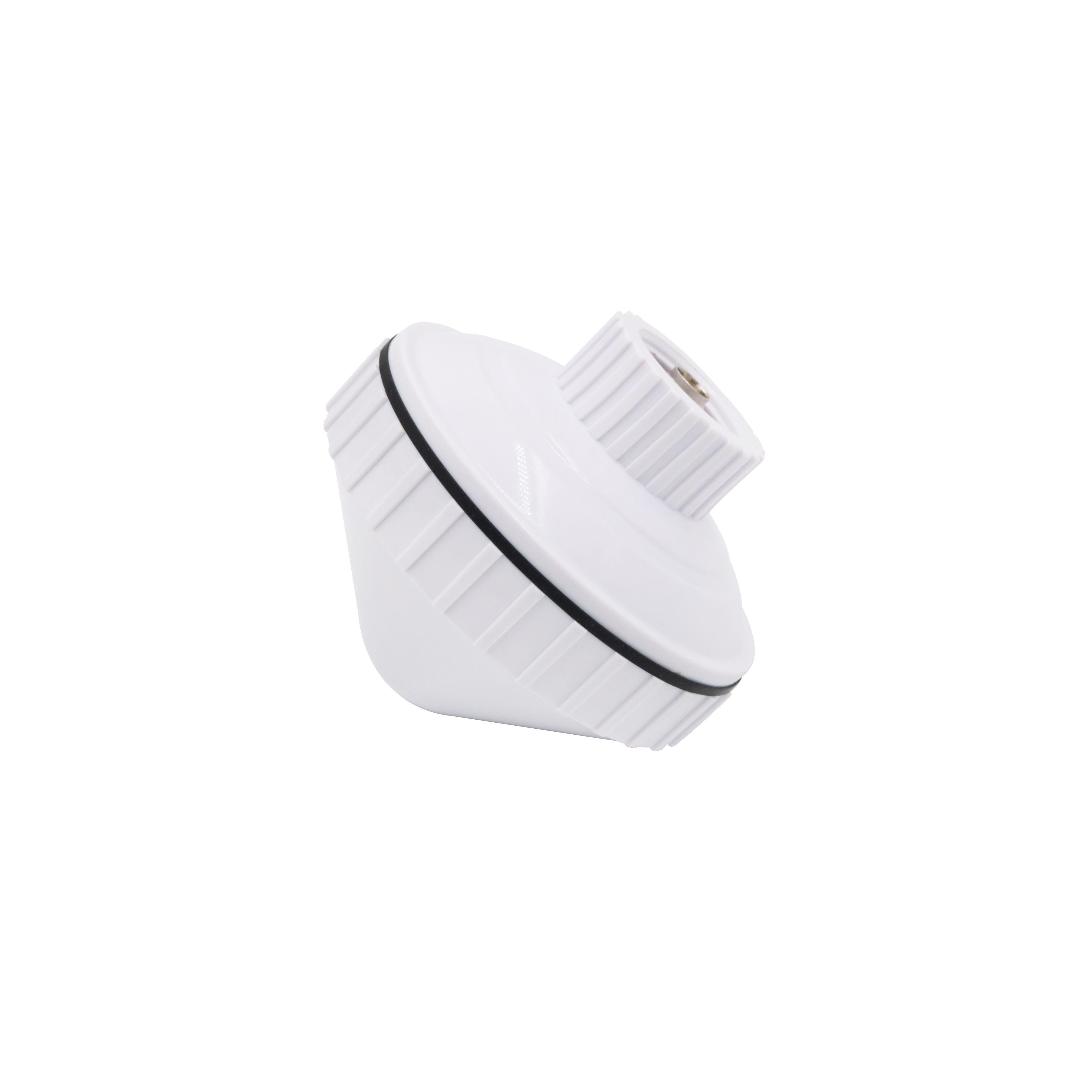
The enclosure of a marine GNSS antenna is designed to protect the internal components from the harsh marine environment. As mentioned earlier, most marine GNSS antennas have a high - level waterproof and dustproof rating, such as IP66 or IP67. The enclosure is typically made of materials like polycarbonate, which is lightweight, strong, and resistant to UV radiation. Some high - end antennas may use more advanced materials, such as carbon - fiber - reinforced composites, to further improve durability and reduce weight.
The shape of the enclosure is also carefully designed. Many marine GNSS antennas have a domed or radome - shaped enclosure. The domed shape helps in preventing water from pooling on the antenna surface, which could potentially affect the signal reception. It also reduces the wind resistance, making the antenna more stable in high - wind conditions. The radome, which is a protective cover made of a dielectric material, allows the satellite signals to pass through with minimal attenuation while protecting the antenna elements inside.
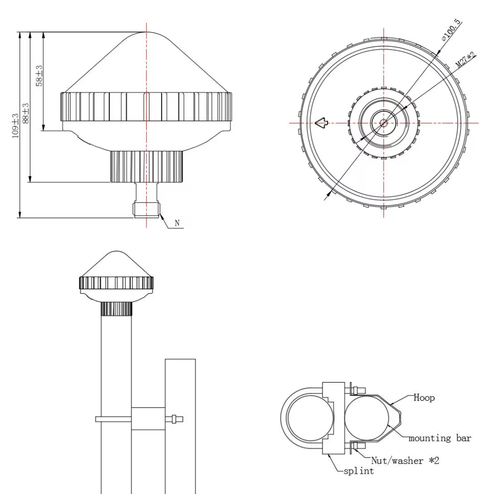
Mounting options for marine GNSS antennas are diverse to accommodate different boat designs and installation requirements. Common mounting methods include pole - mounting, deck - mounting, and mast - mounting. Pole - mounting is a popular choice as it allows the antenna to be placed at a high point, providing better satellite visibility. Deck - mounting is suitable for boats where space is limited, and the antenna can be mounted directly on the deck surface. Mast - mounting is often used on larger vessels, where the antenna can be installed on the mast to gain a better vantage point. The mounting hardware is usually made of stainless steel or other corrosion - resistant materials to ensure long - term reliability.
2.3 Electrical Components
Inside the marine GNSS antenna, there are several electrical components that are essential for its operation. The most important component is the low - noise amplifier (LNA). The satellite signals received by the antenna are extremely weak, typically in the range of - 130 dBm to - 160 dBm. The LNA is used to amplify these signals without adding significant noise, ensuring that the GNSS receiver can accurately process the signals. The gain of the LNA is carefully optimized to balance the signal strength and the noise figure. A higher gain may increase the signal strength but could also introduce more noise, while a lower gain may result in a weak signal that is difficult to process.
Another important electrical component is the filter. Filters are used to remove unwanted signals and interference from the received satellite signals. There are different types of filters used in marine GNSS antennas, such as band - pass filters and surface acoustic wave (SAW) filters. Band - pass filters are designed to allow only the GNSS signals within a specific frequency range to pass through, while blocking signals outside this range. SAW filters, on the other hand, are highly selective and can effectively remove narrow - band interference. They are often used in the front - end of the antenna to protect the LNA from being saturated by strong out - of - band signals.
The antenna may also contain other components such as impedance - matching circuits, which are used to ensure that the antenna is properly matched to the GNSS receiver. This helps in maximizing the power transfer from the antenna to the receiver and reducing signal reflections. Additionally, some advanced marine GNSS antennas may have built - in signal processing capabilities, such as multipath mitigation algorithms, which can further improve the positioning accuracy.
3.1 Satellite Signal Reception
Marine GNSS antennas work by receiving signals transmitted by satellites orbiting the Earth. These satellites continuously broadcast signals that contain information about their position, time, and other parameters. The GNSS antenna's role is to capture these signals and transfer them to the GNSS receiver for processing.
The satellite signals are transmitted in the form of electromagnetic waves in the microwave frequency range. As mentioned earlier, different GNSS constellations operate at different frequencies. For example, GPS satellites transmit signals at L1, L2, and L5 frequencies, GLONASS satellites operate at G1, G2, and G3 frequencies, and Galileo satellites use E1, E5a, E5b, and other frequencies. The marine GNSS antenna is designed to be sensitive to these specific frequencies, allowing it to receive signals from multiple constellations simultaneously.
When the satellite signals reach the antenna, they interact with the antenna elements. The antenna elements are designed to resonate at the frequencies of the satellite signals, which causes an electric current to flow in the elements. This electric current is then converted into an electrical signal that can be transmitted to the GNSS receiver through a coaxial cable or other transmission medium.
3.2 Signal Processing in the Antenna
Once the satellite signals are received by the antenna, they undergo some initial processing within the antenna itself before being sent to the GNSS receiver. This processing is mainly focused on amplifying the weak signals and filtering out unwanted interference.
As described in the design section, the low - noise amplifier (LNA) in the antenna amplifies the received satellite signals. The LNA is designed to have a very low noise figure, which means that it adds minimal noise to the signal during the amplification process. This is crucial because the satellite signals are already extremely weak, and any additional noise could degrade the signal - to - noise ratio and make it more difficult for the GNSS receiver to accurately process the signals.
After amplification, the signals pass through filters. The filters in the antenna are designed to remove various types of interference. There are two main types of interference that the antenna needs to deal with: narrow - band interference and wide - band interference. Narrow - band interference typically comes from sources such as nearby radio transmitters or other electronic devices that operate at specific frequencies. Wide - band interference, on the other hand, can be caused by atmospheric noise, electrical discharges, or other broadband sources. The band - pass filters and SAW filters in the antenna are designed to specifically target and remove these types of interference, ensuring that only the clean GNSS signals are passed on to the GNSS receiver.
3.3 Positioning Calculation by the Receiver
The GNSS receiver, after receiving the processed signals from the antenna, uses a complex algorithm to calculate the position of the boat. The most common method used for positioning is the trilateration method. In trilateration, the receiver measures the distance (range) between itself and at least four satellites.
The distance to each satellite is calculated based on the time it takes for the satellite signal to reach the receiver. Since the satellite signals travel at the speed of light, by measuring the time delay between the signal transmission from the satellite and its reception by the receiver, the receiver can calculate the distance. However, due to various factors such as the inaccuracies in the receiver's clock and the effects of the Earth's atmosphere on the signal propagation, the measured distances are called pseudoranges.
To accurately determine the position (latitude, longitude, and altitude) of the boat, the GNSS receiver uses a system of equations based on the pseudoranges to multiple satellites. By solving these equations simultaneously, the receiver can calculate the precise position of the boat. In addition to positioning, the GNSS receiver can also calculate other parameters such as the speed of the boat, the direction of travel (heading), and the time.
Some advanced GNSS receivers also use additional techniques to improve the positioning accuracy. For example, differential GNSS (DGNSS) techniques use a reference station on the ground that has a known position. The reference station measures the errors in the satellite signals and broadcasts these corrections to the GNSS receiver on the boat. The receiver then uses these corrections to improve the accuracy of its position calculation. Another technique is precise point positioning (PPP), which uses precise satellite orbit and clock information to achieve high - accuracy positioning without the need for a local reference station.
4.1 Advantages
4.1.1 High - Precision Navigation
One of the most significant advantages of boat - mounted marine GNSS antennas is their ability to provide high - precision navigation. With the use of multi - constellation and multi - frequency technology, modern marine GNSS antennas can achieve positioning accuracies of less than a meter in many cases. This level of accuracy is crucial for various marine applications. For example, in commercial shipping, accurate navigation is essential for safe passage through narrow channels, berthing at ports, and avoiding collisions with other vessels. In the fishing industry, precise positioning allows fishermen to accurately locate fishing grounds, reducing fuel consumption and increasing catch efficiency. For recreational boaters, high - precision navigation provides a sense of safety and confidence, especially when exploring unfamiliar waters.
4.1.2 Global Coverage
GNSS systems, including GPS, GLONASS, Galileo, and BeiDou, offer global coverage. This means that regardless of where a boat is located in the world's oceans, as long as there is a clear line of sight to the satellites, the marine GNSS antenna can receive signals and provide navigation information. This is in contrast to some other navigation systems, such as terrestrial radio - based navigation systems, which have limited coverage areas. The global coverage of GNSS antennas makes them ideal for long - distance voyages, international shipping, and exploration in remote areas of the ocean.
4.1.3 Robustness to Environmental Conditions
Marine GNSS antennas are designed to be highly robust to the harsh environmental conditions encountered at sea. Their waterproof and dustproof enclosures, along with corrosion - resistant materials, ensure that they can withstand saltwater, high humidity, strong winds, and extreme temperatures. Additionally, the advanced signal processing techniques used in these antennas, such as multipath mitigation and interference rejection, make them more reliable in challenging environments. For example, in areas with a lot of multipath interference, such as near large coastal cities or in crowded harbors, the antenna's ability to filter out the reflected signals and focus on the direct satellite signals helps in maintaining accurate positioning.
4.1.4 Integration with Other Systems
Marine GNSS antennas can be easily integrated with other onboard systems on a boat. They can provide position, speed, and heading information to navigation displays, chart plotters, autopilots, and other navigation - related equipment. This integration allows for a seamless navigation experience, where all the necessary information is presented in a unified and coordinated manner. For example, the autopilot system can use the position and heading information from the GNSS antenna to automatically steer the boat along a pre - defined route, reducing the workload on the crew and improving the overall safety of the voyage.
4.2 Challenges
4.2.1 Multipath Interference
Multipath interference is one of the major challenges faced by marine GNSS antennas. As mentioned earlier, multipath occurs when the satellite signals bounce off surfaces such as the water, boat hull, or nearby structures before reaching the antenna. These reflected signals can interfere with the direct satellite signals, causing errors in the position calculation. In a marine environment, where there is a large expanse of water that can act as a reflector, multipath interference is particularly prevalent. To mitigate this problem, advanced antenna designs and signal processing techniques are used, such as circularly polarized antennas and multipath mitigation algorithms. However, completely eliminating multipath interference remains a challenge, especially in complex environments.
4.2.2 Interference from Other Devices
There is a growing number of electronic devices on boats, such as radios, radars, and communication systems, which can potentially interfere with the GNSS antenna's signal reception. These devices operate at frequencies that may overlap with the GNSS frequencies, causing interference. For example, a nearby VHF radio transmitter may emit signals that disrupt the GNSS signals received by the antenna. To address this issue, proper shielding and filtering techniques are used in the antenna design. Additionally, regulatory bodies have set limits on the emission levels of electronic devices to minimize interference with GNSS systems. However, ensuring complete interference - free operation in a crowded electromagnetic environment can be difficult.
4.2.3 Satellite Signal Blockage
In some situations, the satellite signals may be blocked, resulting in a loss of signal reception or degraded performance. This can happen when the boat is in a narrow fjord, near tall buildings, or under a bridge. The physical obstructions can prevent the satellite signals from reaching the antenna, or they can cause the signals to be weakened or distorted. To overcome this challenge, some marine GNSS antennas are designed to have a wide field of view, allowing them to receive signals from satellites in different directions. Additionally, backup navigation systems, such as inertial navigation systems, can be used in case of a complete loss of GNSS signal.
4.2.4 Cost - Effectiveness
High - performance marine GNSS antennas, especially those with advanced features such as multi - constellation and multi - frequency capabilities, can be relatively expensive. This cost can be a barrier for some boat owners, particularly those with smaller or budget - conscious vessels. Balancing the need for high - quality, accurate navigation with the cost - effectiveness is a challenge for both antenna manufacturers and boat owners. However, as technology advances and economies of scale come into play, the cost of marine GNSS antennas is gradually decreasing, making them more accessible to a wider range of users.
5.1 Current Applications
5.1.1 Commercial Shipping
In the commercial shipping industry, boat - mounted marine GNSS antennas are essential for safe and efficient navigation. They are used for route planning, collision avoidance, and berthing operations. Precise positioning provided by GNSS antennas allows ships to follow the most optimal routes, reducing fuel consumption and travel time. For example, large container ships use GNSS - based navigation systems to navigate through busy shipping lanes, enter ports accurately, and dock at the appropriate berths. The integration of GNSS antennas with other onboard systems, such as automatic identification systems (AIS) and vessel traffic management systems (VTMS), further enhances the safety and efficiency of commercial shipping operations.
Conclusion
Boat - mounted marine GNSS antennas have become an indispensable component of modern marine navigation, playing a crucial role in ensuring the safety, efficiency, and reliability of various marine operations. From the early days of basic GPS antennas to the current state - of - the - art multi - constellation and multi - frequency models, these antennas have undergone significant advancements in design, performance, and functionality.
In terms of design and construction, the use of advanced antenna elements such as patch and helical antennas, along with robust enclosures made of corrosion - resistant materials and efficient mounting systems, has enabled marine GNSS antennas to withstand the harsh marine environment. The integration of key electrical components like low - noise amplifiers and filters has further improved their ability to receive and process weak satellite signals while minimizing the impact of interference.
The working principles of marine GNSS antennas, which involve receiving satellite signals, processing them within the antenna, and enabling the GNSS receiver to calculate the boat's position using trilateration and other advanced techniques, have been refined over time to deliver high - precision positioning. This high precision, combined with global coverage, robustness to environmental conditions, and ease of integration with other onboard systems, has made these antennas highly advantageous for a wide range of marine applications.
However, marine GNSS antennas also face several challenges, including multipath interference, interference from other electronic devices, satellite signal blockage, and cost - effectiveness. Despite ongoing efforts to mitigate these challenges through advanced design and signal processing techniques, there is still room for improvement.
Looking ahead, the future of boat - mounted marine GNSS antennas is promising, with trends such as integration with 5G technology, miniaturization and increased portability, enhanced anti - interference capabilities, and integration with autonomous vessels expected to drive further innovation. These advancements will not only improve the performance and functionality of marine GNSS antennas but also expand their applications to new areas of marine operations.
In conclusion, boat - mounted marine GNSS antennas have come a long way, and their continued development will be essential for meeting the evolving needs of the marine industry. As technology progresses, these antennas will play an even more critical role in ensuring the safety, efficiency, and sustainability of marine navigation and operations worldwide. Whether it is for commercial shipping, fishing, recreational boating, search and rescue, or marine research, boat - mounted marine GNSS antennas will remain a vital tool for mariners in the years to come.

 86 0755 2819 9597
Lucy Yang | lucy.y@toxutech.com
Nicole Li | nicole@toxutech.com
Dotty Zhao | sales04@toxutech.com
Global Business Director / Sales Team / Global Operations


 En
En Cn
Cn Korean
 Home >


