

-
Products -PCBA Manufacturing RF Connectors RF Cable Assemblys Embedded Antennas External Antennas Positioning Chips and Modules
RF Connectors

RF Cable Assemblys
Embedded Antennas
External Antennas
Positioning Chips and Modules


 Language


Language


The automotive industry is in the midst of a profound transformation, evolving from a collection of mechanical systems into a network of sophisticated software-defined platforms. At the heart of this evolution lies connectivity, and a fundamental pillar of connectivity is location awareness. The Global Navigation Satellite System (GNSS) antenna is the critical interface that enables a vehicle to know its precise position, velocity, and time (PVT), forming the cornerstone for a vast array of modern automotive functionalities. Far more than just enabling turn-by-turn navigation, the automotive GNSS antenna is an unsung hero, enabling safety systems, convenience features, and the autonomous driving revolution.
An automotive GNSS antenna is a specialized type of antenna engineered to operate in one of the most challenging radio frequency (RF) environments imaginable. It must provide reliable, continuous positioning despite being housed within a rapidly moving metal box, surrounded by a growing number of other RF emitters (cellular, WiFi, V2X, radar), and subjected to extreme environmental conditions. Its role has expanded from a simple receiver for navigation to a mission-critical sensor for Advanced Driver-Assistance Systems (ADAS) and future autonomous vehicles (AVs).
The journey of the automotive antenna began with simple passive monopoles or patches mounted externally on the roof or embedded in the rear glass. These were sufficient for basic GPS reception. However, the demands of modern vehicles have necessitated a quantum leap in performance and integration. Today's automotive GNSS antennas are typically active, ceramic patch antennas, highly integrated into the vehicle's aesthetic, most commonly housed within the "shark-fin" module that has become a ubiquitous feature on modern vehicle rooflines. This module is no longer just for GNSS; it is a multi-functional array often combining GNSS, cellular (4G/5G for telematics), satellite radio (SDARS), and sometimes even AM/FM and V2X functionalities.
The operating environment is exceptionally hostile. The vehicle's roof itself acts as a ground plane, but its size and shape are designed for aesthetics and aerodynamics, not optimized for RF performance. Inside the vehicle, the antenna must contend with RF noise generated by inverters, motor controllers, infotainment systems, and a multitude of other electronic control units (ECUs). Externally, the antenna faces signal attenuation from glass and roof lining, multipath reflections from the road surface, other vehicles, and buildings, and extreme environmental conditions ranging from freezing winters to scorching summers, along with exposure to UV radiation, vibration, and chemical contaminants like road salt.
For ADAS and autonomy, the requirements are even more stringent. Lane-keeping assistance, adaptive cruise control, and automated lane changes require not just meter-level accuracy, but consistent, reliable, sub-meter, and eventually centimeter-level accuracy. This demands support for multi-frequency, multi-constellation GNSS (GPS, GLONASS, Galileo, BeiDou) and the ability to utilize correction services (e.g., RTK, SBAS) for enhanced precision. Furthermore, integrity—the ability to self-monitor and provide a trust level for the position solution—becomes paramount. A failure or degradation of the GNSS signal must be communicated instantly to other vehicle systems.
In essence, the modern automotive GNSS antenna is a highly engineered, robust, and intelligent system. It is a key enabler for navigation, emergency call (eCall) systems, stolen vehicle tracking, usage-based insurance, and the seamless connectivity that drivers have come to expect. As vehicles progress towards higher levels of automation, the GNSS antenna evolves from a convenience module to a safety-critical sensor, whose performance and reliability are directly tied to the safety of the vehicle's occupants and other road users. This overview sets the stage for understanding the complex design and operational challenges this component must overcome.
The design and construction of an automotive GNSS antenna is a masterclass in balancing electromagnetic performance, mechanical durability, aesthetic integration, and high-volume manufacturability. Every aspect is optimized to survive and perform reliably on a vehicle for over a decade.
1. Radiating Element: The Ceramic Patch
Material: The heart is a ceramic patch antenna, typically made from a titanium-based ceramic or alumina (Al₂O₃). The dielectric constant (εr) is usually high (e.g., 20-40) to allow for a compact size, fitting within the constrained space of a shark-fin housing.
Multiband Design: Modern antennas must support multiple GNSS bands (L1, L2, L5 for GPS; E1, E5a, E5b for Galileo, etc.). This is achieved through advanced designs like stacked patches (multiple ceramic layers) or a single patch with slot-loading techniques to excite multiple resonant modes, creating a wideband antenna that covers ~1550 MHz to 1610 MHz and often 1160-1300 MHz for L5/E5a/B2a signals.
2. Ground Plane: The Vehicle's Roof
Unlike a standalone antenna with its own ground plane, the automotive antenna uses the vehicle's roof itself. This presents a major design challenge. The roof is a finite, and often irregular, ground plane. Its size and shape significantly impact the antenna's radiation pattern, gain, and efficiency. Antenna designers work closely with vehicle stylists and engineers to ensure the roof section underlying the antenna is sufficient (typically requiring a minimum diameter of ~10-15 cm of uninterrupted metal) and that the antenna is placed optimally, away from roof ribs or sunroof openings that can disrupt the ground plane.
3. Low-Noise Amplifier (LNA)
This is a critical component. The weak GNSS signals (~-130 dBm) require immediate amplification.
Location: The LNA is placed as close as possible to the antenna feed point, often directly on a small PCB beneath the ceramic patch, to boost the signal before any loss occurs in the coaxial cable.
Performance: Automotive LNAs require a very low noise figure (typically < 1 dB) and high gain ( often > 30 dB) to overcome the subsequent cable loss. They must be highly linear to avoid being desensitized by strong out-of-band signals from nearby cellular transmitters often housed in the same module.
Power: The LNA is powered through the coaxial cable via a bias-tee circuit, simplifying the wiring harness.
4. Filtering
The automotive RF environment is incredibly noisy. The antenna assembly incorporates sophisticated filtering:
Bandpass Filters: These are integrated before and/or after the LNA to reject powerful out-of-band signals from cellular services (700 MHz - 3.5 GHz), FM radio (~100 MHz), and radar (24 GHz, 77 GHz). Without this, the GNSS receiver would be overwhelmed.
Surge Protection: The antenna must be protected from voltage transients and electrostatic discharge (ESD), which are common in the automotive electrical system.
5. Housing and Integration: The Shark-Fin
Radome: The entire assembly is housed within a plastic radome, the iconic "shark-fin." The plastic material is critically important: it must be RF-transparent (low loss tangent), withstand UV radiation without degrading or yellowing, be resistant to chemicals (car wash detergents, road salt), and survive impact from stones and hail. Materials like Polycarbonate (PC), Acrylonitrile Styrene Acrylate (ASA), and Polypropylene (PP) are common.
Sealing: The unit is hermetically sealed to IP6K9K (dust-tight and high-pressure, high-temperature water jet resistant) standards to prevent moisture ingress, which would destroy the electronics and detune the antenna.
Multi-Function Integration: The shark-fin rarely houses just GNSS. It is a multi-antenna system (MAS). This means the GNSS element must be carefully isolated from nearby antennas for cellular, SDARS, and V2X to prevent mutual coupling and interference. This is achieved through careful spatial separation, orthogonal polarization, and sometimes specialized isolation materials.
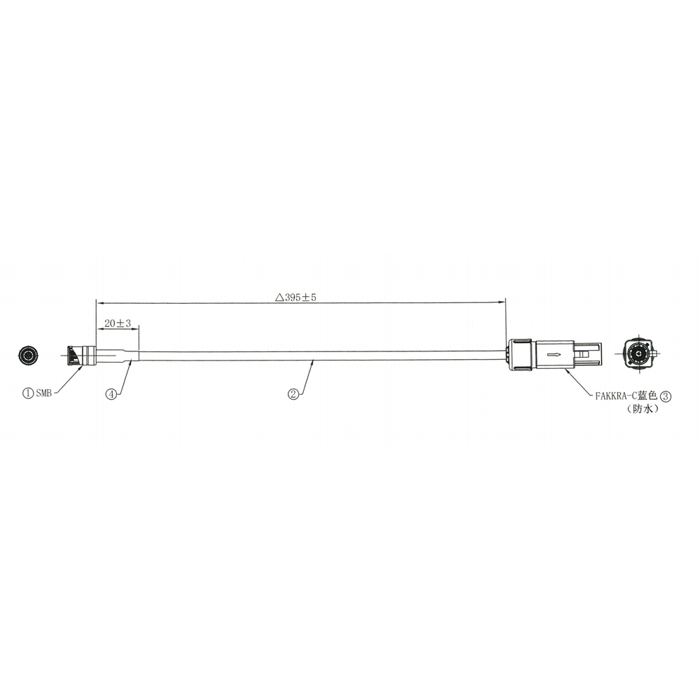
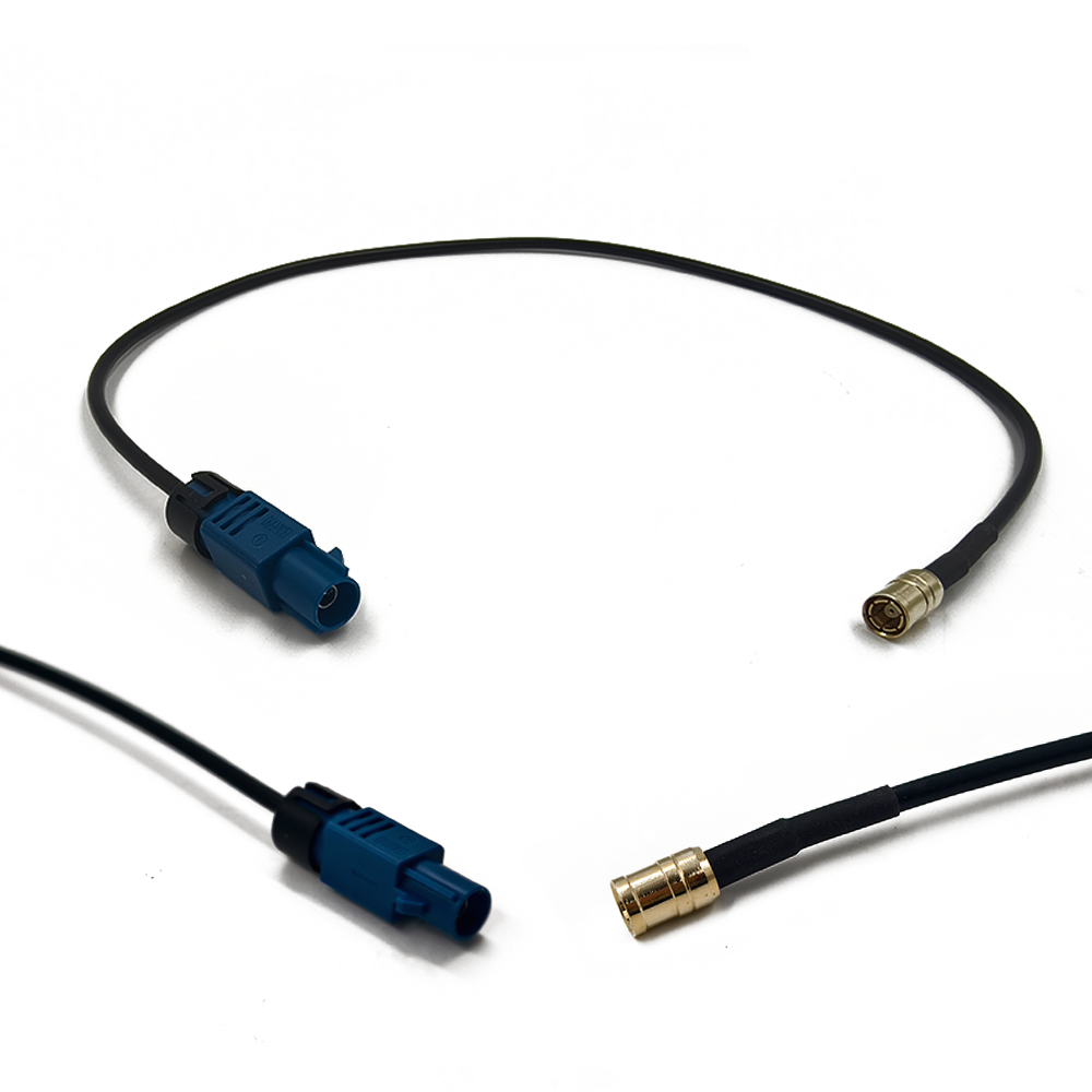
6. Cable and Connector
A low-loss coaxial cable (e.g., RG-174 or a specialized automotive-grade cable) transmits the amplified signal from the roof to the infotainment or telematics unit, often located in the dashboard. The connectors are automotive-grade, designed with positive locking features to resist vibration-induced disconnection and are gold-plated to prevent corrosion.
The construction process is geared for high-volume, automated production while maintaining strict tolerances. The ceramic element is precision-made, the PCB is assembled with automated pick-and-place and soldering, and the final assembly and sealing process is rigorously tested to ensure every unit can survive a lifetime on the road.
The operation of an automotive GNSS antenna is a continuous battle to extract an incredibly weak, desired signal from a cacophony of noise and interference, all while moving at high speed.
1. Signal Reception and Amplification:
The ceramic patch antenna is designed to be most sensitive to signals arriving from above the horizon (the skyward hemisphere), which is where satellites are located. It is typically right-hand circularly polarized (RHCP) to match the polarization of the direct satellite signals and to partially reject left-hand circularly polarized (LHCP) reflected signals (multipath). The tiny currents induced by the satellite signals at the feed point are immediately amplified by the integrated LNA. This first amplification is crucial for establishing a good system noise figure.
2. The Challenge of Multipath:
One of the biggest challenges for a car antenna is multipath. As the vehicle moves, signals reflect off the road, other vehicles, buildings, and even parts of the car itself. These reflected paths are longer than the direct path and arrive at the antenna slightly delayed, causing phase errors that corrupt the precise range measurements. The antenna mitigates this through:
Polarization Discrimination: The antenna's RHCP design provides inherent rejection of reflections, which often have a reversed LHCP component.
Pattern Nulling: The antenna's radiation pattern, shaped by the vehicle's roof ground plane, is designed to have lower gain at very low elevation angles (below 10-15°) where most ground reflections originate.
3. The Battle Against Interference:
The modern car is a rolling RF nightmare for a sensitive GNSS receiver. Key interference sources include:
In-Vehicle Sources: Switch-mode power supplies for infotainment systems, LCD displays, motor controllers for seat and window motors, and high-speed digital data buses (e.g., CAN-FD) all emit broadband noise that can fall within the GNSS band.
Co-located Transmitters: The cellular modem (4G/5G) and V2X radio in the same shark-fin are powerful transmitters whose harmonics can easily desensitize the GNSS receiver if not properly filtered.
The antenna's integrated bandpass filter is the first line of defense, attenuating these out-of-band signals before they can reach the LNA and cause overload or intermodulation distortion.
4. Dynamic Pattern Behavior:
A unique aspect of automotive antennas is that their performance is not static. The antenna's radiation pattern is influenced by the entire vehicle body—the "platform." The pattern can change slightly depending on what is around the car (e.g., driving under a bridge, next to a large truck) and the state of the vehicle itself (e.g., an open sunroof can significantly detune the antenna). Modern GNSS receivers use sophisticated algorithms that can help mitigate some of these effects, but the antenna's inherent stability is the primary factor.
5. Providing a Clean Signal to the Receiver:
The ultimate goal of the antenna system is to deliver a amplified, filtered, and relatively clean GNSS signal to the receiver module located elsewhere in the car. The receiver then performs the tasks of correlation, demodulation, and PVT calculation. The quality of the signal provided by the antenna assembly directly determines the receiver's ability to acquire and track satellites, especially in challenging urban canyon or tree-canopy environments where signal strength is already marginal.
In summary, the antenna works not by magically creating a perfect signal, but by doing the best possible job of preserving the weak signals from space while aggressively rejecting the overwhelming noise and interference generated by the vehicle and its environment. It is a signal conditioning system as much as it is a signal reception system.
Advantages of the Integrated Automotive Approach:
Optimal Placement: The roof is the ideal location for a GNSS antenna. It provides a largely unobstructed 360-degree view of the sky, maximizing the number of satellites in view. It also provides a natural ground plane.
Aesthetic Integration: The shark-fin design is now a accepted and even stylish automotive feature, successfully hiding the technology while minimizing impact on aerodynamics compared to older whip or stubby antennas.
Improved Performance: The integrated LNA ensures a strong signal is sent down the cable to the receiver, overcoming the losses of a long cable run and improving the overall signal-to-noise ratio.
Consolidation and Cost Savings: Integrating multiple antennas (GNSS, cellular, SDARS) into a single module simplifies the wiring harness, reduces the number of parts, and streamlines assembly, ultimately reducing cost despite the complexity of the module itself.
Durability and Reliability: Being housed in a sealed module protects the sensitive electronics from the elements, vibration, and physical damage, ensuring long-term reliability over the vehicle's lifespan.
Challenges and Limitations:
Hostile RF Environment: This is the single greatest challenge. mitigating internal and external RF interference requires complex and expensive filtering and shielding strategies.
Compromised Ground Plane: Vehicle designers prioritize style and structure over RF performance. The available ground plane is often smaller than ideal and can be irregularly shaped, leading to sub-optimal antenna patterns with deeper nulls or reduced gain in certain directions.
Multipath: Despite design efforts, multipath remains a significant source of error for automotive GNSS, especially in urban canyons where signals reflect off glass and steel buildings.
Testing Complexity: Validating antenna performance is incredibly complex and expensive. It requires outdoor drive testing, anechoic chamber testing with a vehicle roof section, and sophisticated simulation software to model the antenna's behavior on the complete car body.
Thermal Management: The shark-fin module is a black box sitting in the sun. Internal temperatures can soar, potentially pushing LNAs and other components beyond their specified operating ranges, affecting gain and noise figure.
Applications:
Navigation: The foundational application, providing turn-by-turn guidance.
Telematics and eCall: Automatically transmitting vehicle location in the event of a crash for emergency response.
Stolen Vehicle Tracking: Allowing authorities to locate a stolen car.
ADAS: Providing absolute position for features like adaptive cruise control, lane keeping, and automated parking. It is a key sensor for sensor fusion, combining with cameras, radar, and LiDAR.
Vehicle-to-Everything (V2X): For safety applications like intersection movement assist, the vehicle must know its position with sub-meter accuracy and high integrity to communicate it reliably to other vehicles and infrastructure.
Usage-Based Insurance (UBI): Monitoring driving behavior and location for insurance purposes.
Future Trends:
High-Precision Positioning for Autonomy: The future is multi-frequency, multi-constellation GNSS coupled with Real-Time Kinematic (RTK) correction services and precise point positioning (PPP) to achieve centimeter-level accuracy in real-time. This will require even more advanced antennas with stable phase patterns.
Deep Sensor Fusion: The GNSS antenna will not work in isolation. Its data will be deeply fused with inertial measurement units (IMUs), wheel odometry, camera data, and radar in a centralized vehicle computer to provide a continuous, robust, and high-integrity position solution, even during short GNSS outages (e.g., in tunnels).
Integrated Inertial Navigation Systems (INS): We will see the integration of micro-electromechanical systems (MEMS) IMUs directly into the antenna module itself, creating a single, calibrated positioning unit.
Enhanced Interference Mitigation: Advanced adaptive filtering and null-steering techniques, perhaps using multiple GNSS elements in an array, to dynamically reject jamming and interference sources.
Standardization of Testing: As safety becomes more critical, standardized methodologies for testing and certifying GNSS antenna performance and integrity in the automotive context will become mandatory.
Conclusion
The automotive GNSS antenna has evolved from a simple add-on for navigation into a complex, highly integrated, and safety-aware sensor system. It is a testament to advanced engineering that such a device can perform its delicate task of listening to whispers from space while operating in the electrically chaotic and physically harsh environment of a modern vehicle.
Its journey mirrors the automotive industry's own shift towards connectivity and automation. No longer an afterthought, the GNSS antenna is now a critical component whose performance directly influences the functionality, safety, and user experience of the vehicle. As we advance towards higher levels of autonomy, the demands on this humble component will only grow, requiring ever-greater levels of precision, reliability, and integrity. It will remain an indispensable, silent navigator, guiding the vehicles of today and enabling the autonomous vehicles of tomorrow.

 86 0755 2819 9597
Lucy Yang | lucy.y@toxutech.com
Nicole Li | nicole@toxutech.com
Dotty Zhao | sales04@toxutech.com
Global Business Director / Sales Team / Global Operations


 En
En Cn
Cn Korean
 Home >


