

-
Products -PCBA Manufacturing RF Connectors RF Cable Assemblys Embedded Antennas External Antennas Positioning Chips and Modules
RF Connectors

RF Cable Assemblys
Embedded Antennas
External Antennas
Positioning Chips and Modules


 Language


Language


In the realm of global positioning, where accuracy and consistency are non-negotiable, the active GPS ceramic antenna emerges as a critical component that bridges the gap between weak satellite signals and precise location data. Unlike passive antennas, which rely solely on their physical structure to capture signals, active GPS ceramic antennas integrate advanced electronics—specifically low-noise amplifiers (LNAs) and filters—directly into their design, ensuring that even the faintest GPS signals are amplified and clarified before reaching the receiver. This article explores the technical architecture, material science, and real-world applications of this specialized antenna, highlighting how its FR4 PCB foundation, copper layers, and ceramic radiating element work in harmony to deliver reliable GPS performance across diverse environments. From smartphones to automotive systems, this antenna exemplifies the engineering precision required to harness signals from satellites orbiting 20,000 kilometers above Earth.
At the core of the active GPS ceramic antenna lies its base material: FR4 PCB, a glass-reinforced epoxy laminate that serves as both the structural backbone and the electrical platform for the antenna’s components. FR4 is chosen for its unique combination of mechanical stability, thermal resistance, and dielectric properties—all essential for GPS applications. GPS signals operate at the L1 frequency (1575.42 MHz), a high-frequency band where the dielectric constant of the PCB material directly influences the antenna’s impedance matching and radiation efficiency. FR4’s dielectric constant (typically 4.2-4.8) is carefully selected to stabilize the antenna’s performance, ensuring that it resonates efficiently at 1575.42 MHz while minimizing signal loss through the substrate.
The board thickness of 1.6 mm is a critical parameter optimized for GPS performance. This thickness provides sufficient rigidity to support the ceramic radiating element, preventing warping that could distort the antenna’s radiation pattern and reduce signal capture efficiency. For GPS antennas, which must detect signals with power levels as low as -160 dBm (equivalent to a 10-watt bulb viewed from 20,000 km), even minor physical misalignment can lead to significant performance degradation. The 1.6 mm FR4 base ensures the ceramic patch remains flat and properly oriented, maximizing its ability to capture signals from GPS satellites across the sky. Additionally, this thickness helps isolate the antenna’s active components (LNAs and filters) from external mechanical stress, preserving their electrical performance in harsh environments such as automotive engine bays or industrial machinery.
FR4’s inherent durability further enhances the antenna’s suitability for diverse applications. Its resistance to moisture, chemicals, and temperature fluctuations, combined with the antenna’s wide operating temperature range (-40°C to 105°C), makes it ideal for use in outdoor, automotive, and industrial settings. Whether exposed to the extreme heat of a desert sun or the freezing cold of a winter storm, the FR4 base ensures the antenna maintains its structural integrity, a critical factor in sustaining consistent GPS reception. This durability is particularly important for applications such as fleet tracking, where antennas must operate reliably in remote or harsh locations.
The active GPS ceramic antenna’s electrical performance is defined by its copper layers, with options for 2-layer, 4-layer, or multi-layer configurations. The copper thickness of 35μm is a standard in RF design, striking a balance between conductivity and manufacturability. Copper’s high electrical conductivity minimizes signal loss in the feed network, the pathway that connects the ceramic patch to the LNA. This is essential for preserving the integrity of weak GPS signals, as even a 1 dB loss can reduce the receiver’s ability to lock onto satellites in challenging conditions.
In a 2-layer configuration, the top copper layer forms the feed network, a precision-designed trace that transfers signals from the ceramic patch to the LNA. The bottom layer serves as a ground plane, a critical feature that reflects RF energy upward toward the sky (where GPS satellites reside) while blocking interference from below (e.g., from a vehicle’s metal body or industrial equipment). For more demanding applications, 4-layer or multi-layer PCBs incorporate additional copper planes for power distribution and shielding. These extra layers isolate the LNA from digital noise generated by nearby electronics—such as processors in smartphones or engine control units in cars—preventing interference that could overwhelm the sensitive GPS receiver. The multi-layer design also allows for more complex filter circuits, which suppress out-of-band signals (e.g., from cellular networks or Wi-Fi) that could otherwise mask the GPS L1 frequency.
The copper’s minimum line width and spacing of 0.15 mm enable intricate feed network designs that ensure optimal impedance matching between the ceramic patch (typically 50 ohms) and the LNA. Impedance mismatches cause signal reflections, reducing the amount of power transferred to the amplifier and degrading sensitivity. In GPS systems, where every decibel of signal strength matters, the precision of these copper traces is critical. The 0.15 mm line width allows for gradual impedance transitions, ensuring the antenna remains matched at 1575.42 MHz, while the tight spacing minimizes crosstalk between the feed network and ground plane. This level of precision is achieved through advanced PCB etching processes, ensuring consistency across mass-produced units—a key requirement for OEM applications in consumer electronics and automotive systems.
Protecting the copper layers is a solder mask available in green, blue, or black, which insulates the traces from oxidation and short circuits. While the color does not affect RF performance, it allows for customization to match device aesthetics or industry standards (e.g., black for automotive antennas, green for consumer electronics). Beneath the solder mask, the copper’s surface roughness (Rz 2.5-3.0) is optimized to enhance solder adhesion during component assembly. A controlled roughness ensures strong bonds between the copper and the LNA’s solder pads, preventing cold joints that could introduce signal loss or intermittent connections. This is particularly important for the LNA, as any degradation in its connection to the feed network directly reduces the antenna’s ability to amplify weak GPS signals.
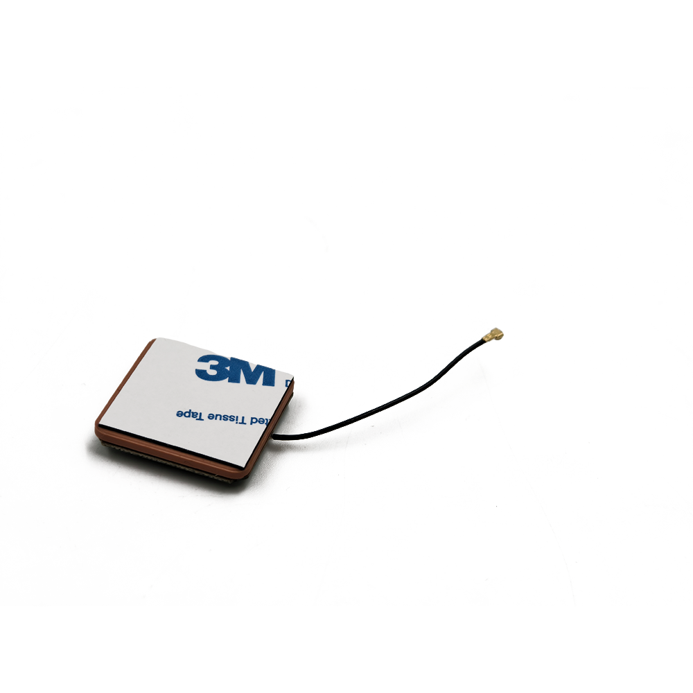
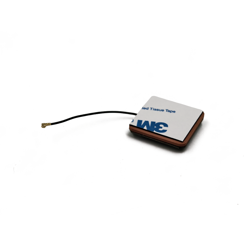
At the heart of the active GPS ceramic antenna is its ceramic radiating patch, a high-dielectric material (typically barium titanate or alumina) that enables compact design without sacrificing performance. Ceramic’s high dielectric constant (20-40) reduces the wavelength of GPS signals, allowing the patch to resonate at 1575.42 MHz despite its small size (typically 10-15 mm in diameter). For example, a ceramic patch with a dielectric constant of 30 can achieve resonance at 1575.42 MHz in a 12 mm x 12 mm footprint, a fraction of the size required for a metal patch antenna (which would need to be approximately 48 mm in length at the same frequency). This miniaturization is critical for integration into compact devices such as smartwatches, fitness trackers, and drone flight controllers, where space is at a premium.
The ceramic patch is bonded to the FR4 PCB, with the copper feed network delivering signals to its edge (edge-fed design) or center (probe-fed design). Edge-fed designs are more common in active GPS antennas, as they simplify impedance matching and reduce cross-polarization—a key consideration because GPS signals are right-hand circularly polarized (RHCP). Cross-polarization can reduce signal strength by 20 dB or more, so the antenna’s design ensures that the ceramic patch maintains RHCP, maximizing signal capture from GPS satellites. The patch’s dimensions are precisely calculated to resonate at 1575.42 MHz, with slight adjustments to its length, width, or thickness fine-tuning its performance to minimize return loss (VSWR) and maximize gain.
As an active antenna, the design incorporates a low-noise amplifier (LNA) to boost weak GPS signals before they reach the receiver. The LNA is typically a GaAs (gallium arsenide) or SiGe (silicon-germanium) device with a noise figure below 1.5 dB, ensuring it amplifies signals without introducing excessive noise—critical for maintaining the signal-to-noise ratio (SNR) required for reliable GPS positioning. The LNA is mounted directly on the FR4 PCB, with minimum hole size of 0.2 mm facilitating secure surface-mount connections. These small holes accommodate the LNA’s fine leads, allowing for compact placement close to the ceramic patch to minimize signal loss in the feed network.
In addition to the LNA, active GPS ceramic antennas include band-pass filters that suppress interference from frequencies outside the GPS L1 band. For example, a filter centered at 1575.42 MHz with a 20 MHz bandwidth will block cellular signals at 1800 MHz or Wi-Fi signals at 2400 MHz, preventing them from overwhelming the LNA. This filtering is essential in urban environments, where RF congestion is high, and in automotive applications, where nearby radar systems (24 GHz) or infotainment radios (FM 88-108 MHz) can generate interference. The combination of LNA and filter transforms the antenna from a passive receiver into an intelligent signal processor, significantly improving performance in challenging conditions such as urban canyons or dense foliage.
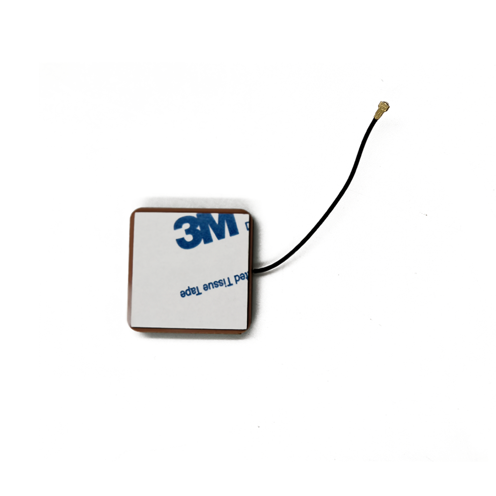
The antenna’s surface finishing: HASL (Lead-Free) ensures long-term reliability by protecting exposed copper surfaces from oxidation. HASL (Hot Air Solder Leveling) applies a thin layer of lead-free solder to the copper, which melts during component assembly to form strong, low-resistance connections. This process is compatible with modern lead-free manufacturing standards, ensuring compliance with RoHS directives in regions like the European Union and China. The solder layer also enhances the antenna’s durability, withstanding thermal cycling during operation and preventing corrosion in humid environments—critical for outdoor applications such as agricultural sensors or marine navigation systems.
The board size of 43.5 mm x 25 mm x 1.6 mm reflects the antenna’s compact design, a key advantage for integration into space-constrained devices. This footprint accommodates the ceramic patch, LNA, filter, and copper ground plane without excessive bulk, making it suitable for applications ranging from smartwatches to vehicle telematics units. Despite its small size, the antenna maintains a sufficiently large ground plane to ensure a low-profile radiation pattern, which minimizes signal blockage by the device itself. For example, in a smartphone, the antenna’s compact size allows it to be mounted near the top edge, where it has an unobstructed view of the sky, while the ground plane prevents signal absorption by the device’s battery or display.
The silkscreen color (white or yellow) is applied over the solder mask, providing visual markers for component placement, test points, and orientation. While not affecting RF performance, the silkscreen is critical for manufacturing quality control, ensuring the LNA, filter, and ceramic patch are positioned correctly during assembly. In high-volume production, clear silkscreen markings reduce placement errors, which could otherwise lead to impedance mismatches or reduced sensitivity. For example, a misaligned LNA could increase the distance from the ceramic patch, introducing additional signal loss in the feed network.
Thermal management is a key consideration in active GPS ceramic antennas, as the LNA generates heat during operation. The FR4 PCB’s thermal conductivity of 1.0-1.5 W/mK allows this heat to dissipate efficiently, preventing the LNA from exceeding its operating temperature range (-40°C to 105°C). In devices where the antenna is enclosed (e.g., a car’s dashboard), the PCB acts as a heat spreader, transferring heat to the surrounding housing. For high-power LNAs, the ground plane can be connected to a metal heatsink, further enhancing thermal dissipation. This thermal efficiency ensures the LNA maintains its low noise figure even during extended operation, a critical factor in preserving positioning accuracy over time.
Safety and compliance are integral to the antenna’s design, as evidenced by its UL94 V-0 flame retardant rating. This certification ensures the FR4 PCB resists ignition and self-extinguishes within 10 seconds if exposed to flame, reducing fire risk in enclosed devices such as automotive infotainment systems or industrial control panels. The UL94 V-0 rating is particularly important for applications where the antenna is near other heat-generating components, ensuring it does not contribute to fire propagation.
The antenna’s compliance with IPC-A-600 Class 2 standards underscores its quality and reliability. IPC-A-600 is the global benchmark for PCB acceptability, with Class 2 specifying requirements for dedicated service electronics where high reliability is needed but continuous operation is not critical (e.g., consumer devices, automotive systems). Compliance ensures the antenna meets strict criteria for copper adhesion, solder mask coverage, and via quality, minimizing the risk of performance degradation or failure. For example, IPC-A-600 Class 2 requires copper traces to have no more than 5% voids, ensuring low resistance in the feed network.
For environmental compatibility, the antenna offers RoHS compliance (Yes/No) options, allowing manufacturers to select versions that meet regional regulations restricting hazardous substances. RoHS-compliant antennas exclude lead, mercury, and cadmium, making them suitable for sale in the EU, China, and other regulated markets. This flexibility ensures the antenna can be integrated into global products without compromising compliance, a key advantage for OEMs operating in international markets.
The active GPS ceramic antenna’s functional application spans a wide range of industries, each leveraging its precision and compact design:
Automotive: Integrated into car navigation systems and advanced driver-assistance systems (ADAS), the antenna enables real-time mapping, lane guidance, and emergency services (e.g., eCall). Its wide operating temperature range (-40°C to 105°C) withstands the extreme heat of vehicle interiors and cold of winter, while multi-layer shielding reduces interference from the car’s electronics.
Consumer Electronics: Used in smartphones, smartwatches, and fitness trackers, the antenna provides location data for mapping, fitness tracking, and geofencing. Its small size (43.5 mm x 25 mm) fits within tight device enclosures, while the LNA ensures reliable reception even when the device is indoors or covered by the user’s hand.
Drones and UAVs: Mounted on drone frames, the antenna enables precise positioning for autonomous flight, waypoint navigation, and aerial mapping. Its lightweight design (typically <10 grams) minimizes impact on flight time, while its compact size allows for integration without disrupting the drone’s aerodynamics.
Industrial IoT (IIoT): Deployed in smart meters, asset trackers, and logistics devices, the antenna provides location-tagged data for inventory management, route optimization, and theft prevention. Its rugged design and RoHS compliance make it suitable for long-term outdoor deployment, while the filter suppresses interference from industrial machinery.
Marine and Outdoor Recreation: Used in boats, hiking watches, and camping gear, the antenna supports navigation in remote areas where cellular coverage is unavailable. Its weather-resistant design and wide temperature range ensure reliability in rain, snow, and extreme temperatures.
In real-world performance, the active GPS ceramic antenna excels in challenging environments where passive antennas struggle. In urban canyons, where tall buildings block or reflect GPS signals, the LNA amplifies weak direct signals, while the filter suppresses reflections (multipath interference) that can cause positioning errors of 10 meters or more. In dense foliage, the antenna’s sensitivity allows it to capture signals that penetrate leaves and branches, maintaining accuracy within 5-10 meters. For applications requiring higher precision—such as surveying or autonomous vehicles—the antenna can be paired with differential GPS (DGPS) systems, leveraging its low noise figure to resolve position errors down to centimeters.
In conclusion, the active GPS ceramic antenna represents a fusion of material science and RF engineering, optimized to deliver reliable positioning by harnessing weak signals from orbiting satellites. Its FR4 PCB base provides structural stability and dielectric performance, while copper layers enable efficient signal transfer and shielding. The ceramic patch ensures compact design without sacrificing sensitivity, and active components (LNA and filter) amplify weak signals while suppressing interference. With features such as lead-free HASL finishing, UL94 V-0 flame resistance, and RoHS compliance, the antenna meets global standards for reliability and safety. From consumer devices to industrial systems, the active GPS ceramic antenna is a cornerstone of modern navigation, enabling the precision and availability required in an increasingly mobile world. As GPS technology evolves—with the introduction of new frequencies like L5 (1176.45 MHz)—this antenna’s flexible design ensures it will remain a critical component in the next generation of positioning systems.

 86 0755 2819 9597
Lucy Yang | lucy.y@toxutech.com
Nicole Li | nicole@toxutech.com
Dotty Zhao | sales04@toxutech.com
Global Business Director / Sales Team / Global Operations


 En
En Cn
Cn Korean
 Home >


