

-
Products -PCBA Manufacturing RF Connectors RF Cable Assemblys Embedded Antennas External Antennas Positioning Chips and Modules
RF Connectors

RF Cable Assemblys
Embedded Antennas
External Antennas
Positioning Chips and Modules


 Language


Language


In an era defined by connectivity and location-aware technology, the Global Positioning System (GPS) and other Global Navigation Satellite Systems (GNSS) have become an invisible utility as critical as electricity or the internet. At the forefront of capturing this capability for countless devices is the Active GPS Ceramic Antenna—a small, unassuming, yet remarkably sophisticated component that serves as the critical gateway between orbiting satellites and the electronic devices we rely on daily. This overview delves into the fundamental role of this technology, distinguishing it from its counterparts and highlighting its ubiquity.
An Active GPS Ceramic Antenna is a type of antenna specifically engineered to receive the extremely weak radio frequency (RF) signals transmitted by GNSS satellites. Its name describes its core attributes:
Active: It incorporates an integrated Low-Noise Amplifier (LNA) to boost the faint satellite signals immediately upon reception, before any significant signal loss occurs.
GPS: While often used generically, it's primarily designed for the GPS L1 frequency (1575.42 MHz), though modern versions are frequently multi-band, supporting GLONASS, Galileo, and BeiDou.
Ceramic: The radiating element is crafted from a ceramic substrate, chosen for its specific dielectric properties that allow for a compact, efficient, and high-performance design.
The signals from GNSS satellites are astonishingly weak by the time they traverse over 20,000 kilometers from Medium Earth Orbit to the Earth's surface. With a received power level as low as -160 dBW (decibel-watts), they are literally buried beneath the thermal noise floor of electronic systems. A passive antenna, which simply captures this signal, would then send it down a lossy coaxial cable to a receiver, often degrading it beyond usable levels. This is where the "active" component becomes indispensable. The integrated LNA provides significant gain (often 25-30 dB), amplifying the signal to a level where it can withstand the cable loss and be effectively processed by the downstream receiver.
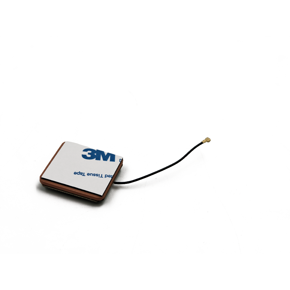
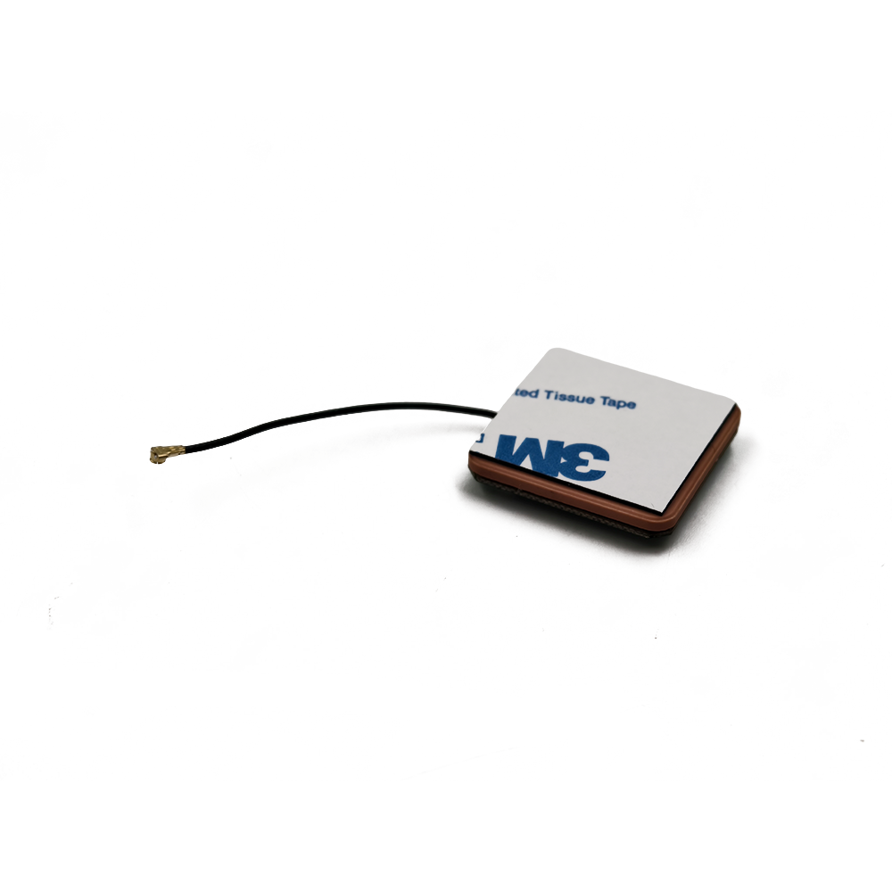
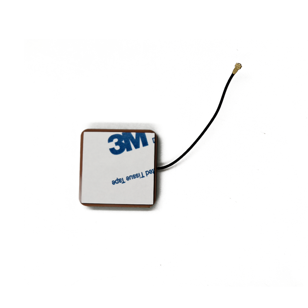
These antennas are the cornerstone of miniaturized GNSS technology. Their compact form factor, often a square patch measuring 25x25mm or smaller, makes them ideal for integration into space-constrained consumer and industrial products. Unlike large helical or quadrifilar antennas, the ceramic patch antenna provides a low-profile, aesthetically pleasing solution that can be easily mounted on a printed circuit board (PCB) or housed within a device's plastic enclosure.
The applications are virtually endless. From the smartphone in your pocket and the wearable on your wrist to the tracking device on a shipping container, the drone in the sky, and the navigation system in your car, the active GPS ceramic antenna is the most common enabler of location services. It represents the perfect marriage of materials science, RF engineering, and mass production, delivering a high-performance, cost-effective solution that has democratized access to precise positioning and timing for the entire world.
The design and construction of an active GPS ceramic antenna are a meticulous process of balancing electromagnetic performance, physical robustness, and manufacturability. It is a multi-layered structure where each component plays a critical role.
1. The Ceramic Patch (Radiating Element):
The heart of the antenna is the ceramic block itself. This is not ordinary pottery clay but a precisely engineered material.
Dielectric Constant (Dk or εr): The ceramic is formulated to have a very high dielectric constant, typically ranging from 20 to over 40. A high Dk effectively "slows down" the electromagnetic waves, allowing the antenna to be electrically large (resonant) while being physically small. This is the key to miniaturization.
Quality Factor (Q): The ceramic must have a low loss tangent, meaning it has a high Q factor. This ensures that minimal energy is lost as heat within the dielectric material itself, maximizing radiation efficiency.
Manufacturing: The ceramic powder is pressed and sintered at high temperatures into a precise, flat block. The top surface is then coated with a silver or other conductive layer, which is photolithographically etched to form the specific radiating patch pattern.
2. The Ground Plane:
Beneath the ceramic patch lies a critical and non-negotiable component: the ground plane. This is a continuous layer of conductive material (typically copper on the PCB) that must extend significantly beyond the edges of the patch.
Function: The ground plane acts as an electrical mirror, creating the image of the patch that completes the resonant structure. It directs the antenna's radiation pattern upward, away from the device it's mounted on.
Size: The size of the ground plane is paramount. A ground plane that is too small will detune the antenna, shifting its resonant frequency, drastically reducing its bandwidth, and distorting its radiation pattern. As a rule of thumb, the ground plane should extend at least a quarter-wavelength (~40mm for GPS L1) beyond the patch edge in all directions, though clever design can mitigate this requirement.
3. The Low-Noise Amplifier (LNA):
This is the "active" element. The LNA is a semiconductor amplifier circuit placed directly in the signal path after the ceramic patch.
Location: It is typically mounted on the PCB immediately adjacent to the antenna's feed point or, in more integrated designs, can be placed on a separate layer beneath the patch.
Key Parameters:
Gain: Typically 25-30 dB. This amplifies the tiny signal to a robust level.
Noise Figure (NF): This is perhaps the most critical spec. A low NF (e.g., <1.5 dB) means the amplifier adds very little of its own noise to the signal, preserving the fragile signal-to-noise ratio (SNR).
Linearity: Measured by Input Third-Order Intercept Point (IIP3), it defines the amplifier's ability to handle strong interfering signals without overloading (desensitization).
4. RF Feed and Matching Network:
The signal from the patch is transferred to the LNA via a carefully designed feed mechanism, such as a probe feed or a microstrip line. A matching network, consisting of tiny capacitors and inductors, ensures maximum power transfer by impedance-matching the antenna (typically 50 Ohms) to the input of the LNA.
5. Shielding and Shielding Can:
The entire assembly is often covered by a metal shield or "can." This serves two purposes:
It protects the delicate LNA from external electromagnetic interference (EMI).
It prevents the LNA from radiating noise back onto the antenna or other parts of the device's circuitry, which could cause de-sense.
6. External Housing and Connectors:
For external antennas, the ceramic patch, LNA, and supporting circuitry are housed in a plastic radome. The radome material is carefully selected to be RF-transparent (low dielectric loss) and protective against environmental factors like UV radiation, moisture, and physical impact. A coaxial connector (like an SMA or TNC) provides the interface to the receiver.
The operation of an active GPS ceramic antenna is a process of efficient capture, immediate amplification, and clean delivery.
1. Signal Reception and Resonance:
The ceramic patch antenna is a resonant structure. Its physical dimensions are precisely calculated to be exactly half a wavelength (electrically, due to the high Dk) at the target frequency of 1575.42 MHz. When the RF waves from GPS satellites impinge upon the patch, they induce a standing wave of electrical current on its surface. This oscillation efficiently converts the electromagnetic energy into an electrical current at the antenna's feed point. The antenna is designed for Right-Hand Circular Polarization (RHCP) to match the polarization of the satellite signals, which provides a inherent degree of rejection for reflected (and often polarity-flipped) multipath signals.
2. Immediate Low-Noise Amplification:
The electrical signal generated at the feed point is incredibly weak, typically around -130 dBm. This signal is immediately fed into the integrated LNA. The LNA's primary job is to apply significant gain to this signal while contributing the absolute minimum amount of additional noise. This is crucial because any signal, no matter how much it is amplified, cannot be recovered if its SNR falls below a certain threshold. By amplifying the signal before it enters the lossy transmission line (the cable), the active antenna effectively "overpowers" the subsequent cable loss. For example, a 3-meter cable might have 6 dB of loss. Without the LNA, the signal would be attenuated to uselessness. With a 26 dB gain LNA, the signal enters the cable at a robust -104 dBm, and after 6 dB of cable loss, it arrives at the receiver at -110 dBm—a perfectly usable level.
3. Filtering and Delivery:
Most active antennas also incorporate a bandpass filter, either before or after the LNA. This filter is centered on the GNSS band (e.g., 1575.42 MHz ± 10 MHz) and serves to reject powerful out-of-band interference from cellular signals (e.g., 4G/5G), Wi-Fi, Bluetooth, and other transmitters that could overload the sensitive LNA or the GPS receiver itself. The now-amplified and filtered signal is sent through the coaxial cable to the GNSS receiver module.
4. The Role of the Receiver:
The antenna's job ends at delivering the RF signal. The receiver then performs the complex tasks of downconverting the signal to a lower frequency, digitizing it, and using correlation techniques to search for and lock onto the spreading codes of individual satellites. It then demodulates the navigation message, calculates pseudoranges, and finally solves the geometric equations to determine precise position, velocity, and time (PVT). The quality of the RF signal provided by the active antenna directly determines how quickly the receiver can achieve a fix (Time To First Fix - TTFF) and the accuracy and stability of the resulting PVT solution.
Advantages:
Superior Signal-to-Noise Ratio (SNR): The integrated LNA is the single biggest advantage, overcoming cable losses and providing a strong, clean signal to the receiver, which is essential for acquiring and tracking weak satellite signals.
Miniaturization: The use of high-Dk ceramic allows for a very small physical footprint, enabling integration into modern compact devices where space is at a premium.
Design Flexibility: They can be supplied as standalone components for PCB mounting (chip antennas) or as complete modules in a housing. This flexibility allows engineers to choose the best integration method for their product.
Good Multipath Rejection: The inherent nature of patch antennas, especially when mounted over a proper ground plane, provides a good front-to-back ratio, making them less susceptible to signals reflected from below or behind the antenna.
Cost-Effectiveness at Scale: Due to their simple structure and suitability for automated surface-mount technology (SMT) assembly, they can be manufactured in massive volumes at a very low unit cost.
Challenges and Limitations:
Ground Plane Dependency: This is the most significant design challenge. Performance is heavily dependent on the size and quality of the ground plane. Placing the antenna too close to the edge of a PCB or on a poorly designed ground plane will severely degrade performance.
Limited Bandwidth: The high-Q resonant nature of the ceramic patch gives it a relatively narrow bandwidth. While sufficient for single-band GPS L1, it becomes a challenge for designing multi-band antennas (e.g., L1+L5) on a single ceramic patch, often requiring more complex designs with multiple feeds.
Fragility: While the ceramic itself is hard, it is also brittle. Mechanical shock from drops or impacts can crack the ceramic substrate, rendering the antenna useless. This necessitates careful handling during assembly and robust product design.
Temperature Sensitivity: The dielectric constant of the ceramic material can change with temperature, which can cause a slight drift in the antenna's resonant frequency. High-quality antennas are designed with materials that minimize this drift.
Susceptibility to Interference: While they have filtering, the proximity of the antenna to other transmitters in a device (e.g., a 5G modem) can lead to interference, requiring careful board layout and additional shielding.
Applications:
Consumer Electronics: Smartphones, smartwatches, fitness trackers, digital cameras, and personal navigation devices.
Automotive: In-car navigation systems, telematics control units (TCUs) for emergency calling (e.g., eCall), and usage-based insurance dongles.
Asset Tracking: Logistics and supply chain tracking devices for containers, trucks, and high-value assets.
Drones (UAVs): Navigation, flight stabilization, and return-to-home functions.
Industrial and IoT: Precision timing for network synchronisation, agricultural guidance, and marine navigation.
Future Trends:
Multi-Band/Multi-Constellation Integration: The future is moving beyond single-band GPS L1. Newer antennas are being designed to support L5, L2C, and other GNSS bands (Galileo E1/E5a, BeiDou B1/B2) on a single ceramic patch. This requires innovative designs like stacked patches or slots to achieve wider bandwidth.
Enhanced Integration (AiP): The trend is towards further miniaturization and integration. Antenna-in-Package (AiP) technology, where the antenna is embedded directly into the IC package of the GNSS receiver, is an emerging frontier, though it presents significant technical challenges for GNSS due to performance requirements.
Improved Interference Robustness: With the RF spectrum becoming increasingly crowded, future designs will incorporate more advanced filtering and potentially integrated filtering techniques to combat jamming and interference from nearby services.
"Smart" or Adaptive Antennas: Research is ongoing into integrating basic beamforming or null-steering capabilities at the consumer level, using multiple ceramic patch elements to electronically mitigate interference and multipath.
Materials Science Advances: Development of new ceramic compounds with more stable temperature performance and even higher dielectric constants to enable further miniaturization without sacrificing bandwidth or efficiency.
Conclusion
The active GPS ceramic antenna is a masterpiece of practical engineering. It solves a fundamental physical problem—the capture of incredibly weak signals from space—with an elegant and manufacturable solution. Its combination of the passive resonant properties of specialized ceramics with the active gain of solid-state amplification has been the key catalyst for the proliferation of location technology across the globe.
While often hidden from view and overlooked in favour of the digital magic performed by the receiver, its role is absolutely foundational. It determines the ultimate performance ceiling of any GNSS system. A poor antenna will irrevocably corrupt the signal before the best receiver in the world even has a chance to process it.
As technology advances towards more demanding applications like autonomous vehicles, advanced drone navigation, and pervasive IoT, the requirements for GNSS performance will only intensify. The humble active ceramic antenna will continue to evolve, embracing multi-band support, tighter integration, and smarter signal processing to meet these challenges. It will remain, for the foreseeable future, the indispensable and unsung hero at the frontier of our interaction with the satellite constellation, silently and efficiently bridging the vast gap between orbit and Earth.

 86 0755 2819 9597
Lucy Yang | lucy.y@toxutech.com
Nicole Li | nicole@toxutech.com
Dotty Zhao | sales04@toxutech.com
Global Business Director / Sales Team / Global Operations


 En
En Cn
Cn Korean
 Home >


