

-
Products -PCBA Manufacturing RF Connectors RF Cable Assemblys Embedded Antennas External Antennas Positioning Chips and Modules
RF Connectors

RF Cable Assemblys
Embedded Antennas
External Antennas
Positioning Chips and Modules


 Language


Language


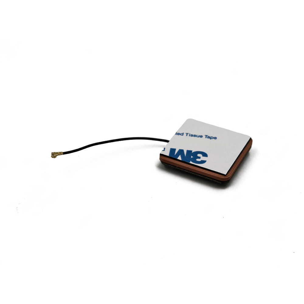

In the realm of radio frequency (RF) engineering, the active ceramic patch antenna stands as a testament to the marriage of material science and precision manufacturing. Designed specifically for AM/FM radio signal reception, this antenna combines the efficiency of a ceramic radiating element with the functionality of an active PCB (printed circuit board) to deliver reliable performance across the 530 kHz to 108 MHz frequency range. This article delves into the technical specifications, design nuances, and practical applications of this specialized antenna, highlighting how its FR4 PCB base, copper layers, and active components work in harmony to capture and amplify weak radio signals. From consumer electronics to industrial communication systems, the active ceramic patch antenna redefines consistency in AM/FM reception, even in challenging environments.
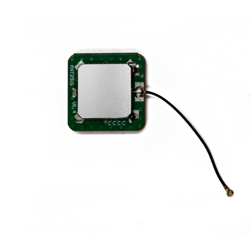
At the core of the active ceramic patch antenna lies its base material: FR4 PCB, a glass-reinforced epoxy laminate that forms the structural and electrical foundation of the device. FR4 is a staple in electronics manufacturing, prized for its exceptional mechanical strength, thermal stability, and dielectric properties—attributes that make it ideal for antenna applications. For AM/FM reception, where signal wavelengths range from 2.78 meters (FM 108 MHz) to 566 meters (AM 530 kHz), the dielectric constant of FR4 (typically 4.2-4.8) helps stabilize the antenna’s impedance and radiation pattern, ensuring consistent performance across the broad frequency spectrum.
The FR4 PCB’s board thickness of 1.6 mm is a critical parameter, carefully chosen to balance structural rigidity with RF performance. This thickness provides sufficient mechanical support for the ceramic patch and active components (such as amplifiers and filters) while minimizing signal loss through the substrate. In AM bands, where longer wavelengths can penetrate obstacles more easily but require larger antenna structures, the 1.6 mm thickness helps maintain the antenna’s compact form factor without sacrificing reception range. For FM bands, which rely on line-of-sight propagation, the rigid PCB ensures the ceramic patch remains properly aligned, maximizing signal capture from nearby transmitters.
Beyond structural support, the FR4 material contributes to the antenna’s durability. Its inherent resistance to moisture, chemicals, and temperature fluctuations makes it suitable for use in diverse environments, from humid consumer devices to industrial enclosures. When combined with the antenna’s wide operating temperature range (-40°C to 105°C), the FR4 base ensures reliable performance in extreme conditions, a key advantage for outdoor or automotive applications.
The antenna’s electrical performance is largely defined by its copper layers, with options for 2 layers, 4 layers, or multi-layer configurations. The copper thickness of 35μm (micrometers) is a standard choice in RF design, providing an optimal balance between conductivity and etching precision. Copper is an excellent conductor of electricity, with low resistance that minimizes signal loss—critical for AM/FM reception, where weak signals must be preserved to ensure clear audio.
In a 2-layer configuration, the top copper layer forms the radiating element’s feed network, connecting the ceramic patch to the active components (such as low-noise amplifiers, LNAs). The bottom layer serves as a ground plane, a crucial feature that shapes the antenna’s radiation pattern by reflecting RF energy upward toward the ceramic patch. This ground plane also reduces interference from nearby electronics, which can disrupt AM/FM signals with electromagnetic noise. For more complex designs, 4-layer or multi-layer PCBs integrate additional copper layers for shielding, power distribution, or signal routing, isolating sensitive RF paths from digital components and further enhancing performance.
The copper’s minimum line width and spacing of 0.15 mm highlight the precision of the manufacturing process. These tight tolerances allow for intricate feed network designs that match the ceramic patch’s impedance (typically 50 ohms) to the active components, minimizing signal reflection and maximizing power transfer. In AM bands, where impedance can vary significantly with frequency, the fine copper traces enable gradual impedance matching, ensuring the antenna remains efficient even at the lower end of the spectrum (530 kHz). For FM frequencies, the precise line spacing reduces crosstalk between the feed network and ground plane, preserving the integrity of weak signals from distant transmitters.
The copper layers are protected by a solder mask, available in green, blue, or black, which insulates the traces from oxidation and short circuits. The solder mask’s color does not affect RF performance but allows for customization to match device aesthetics or industry standards (e.g., green for consumer electronics, black for automotive applications). Beneath the solder mask, the copper’s surface roughness (Rz 2.5-3.0) is optimized to enhance solder adhesion during component assembly while minimizing signal loss. A controlled roughness ensures strong bonds between the copper and solder, preventing cold joints that could degrade electrical connections in active components like LNAs.
At the heart of the antenna is its ceramic patch, a high-dielectric material (typically barium titanate or alumina) that forms the primary radiating element. The ceramic’s high dielectric constant (often 20-40) reduces the wavelength of the RF signal, allowing the patch to resonate at AM/FM frequencies despite its small size. For example, a ceramic patch measuring just a few centimeters can effectively radiate at 100 MHz, a feat that would require a much larger metal element without the ceramic’s dielectric properties.
The ceramic patch is bonded to the FR4 PCB, with the copper feed network delivering RF energy to its edge or center, depending on the design. This feed mechanism excites the patch, causing it to radiate electromagnetic waves that capture AM/FM signals from the air. The patch’s dimensions are carefully calculated to resonate at specific frequencies within the AM/FM spectrum, with adjustments to its length, width, or thickness tuning it to cover the entire 530 kHz-108 MHz range.
As an active antenna, the design incorporates electronic components that amplify and filter incoming signals, addressing the inherent challenges of AM/FM reception. AM signals, in particular, are prone to noise and interference, while FM signals can suffer from multipath distortion (signal reflections from buildings or terrain). The integrated LNA boosts weak signals (typically by 10-20 dB) before they reach the receiver, improving sensitivity and extending the antenna’s effective range. Filters (such as band-pass filters) suppress out-of-band interference, ensuring that only AM/FM frequencies are passed to the receiver—critical in environments with high RF congestion, such as urban areas.
The active components are mounted on the FR4 PCB, with minimum hole size of 0.2 mm facilitating secure through-hole or surface-mount connections. These small holes accommodate fine leads for components like capacitors, inductors, and ICs (integrated circuits), ensuring compact placement without compromising electrical performance. The combination of the ceramic patch and active circuitry results in an antenna that outperforms passive designs, especially in weak-signal conditions.
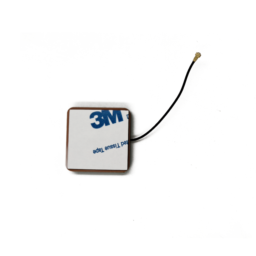
The antenna’s surface finishing: HASL (Lead-Free) is a key manufacturing detail that ensures long-term reliability. HASL (Hot Air Solder Leveling) applies a thin layer of solder to exposed copper surfaces, protecting them from oxidation and ensuring good solderability during assembly. The lead-free formulation complies with environmental regulations (such as RoHS) and is compatible with modern lead-free soldering processes, making the antenna suitable for global markets. This surface finish also enhances the antenna’s durability, withstanding repeated thermal cycles during operation without degrading electrical connections.
The board size of 43.5 mm x 25 mm x 1.6 mm reflects the antenna’s compact design, a critical feature for integration into space-constrained devices. This small footprint allows the antenna to be embedded in consumer electronics such as portable radios, smart speakers, or car infotainment systems, where size and weight are key design considerations. Despite its compactness, the antenna maintains sufficient surface area for the ceramic patch, ground plane, and active components, ensuring it does not sacrifice performance for size.
The silkscreen color (white or yellow) is applied over the solder mask, providing visual identification for components, test points, and orientation markers. While not affecting RF performance, the silkscreen aids in manufacturing and quality control, ensuring components are placed correctly and simplifying troubleshooting. In high-volume production, clear silkscreen markings reduce assembly errors, maintaining consistent performance across antenna units.
The antenna’s thermal management is enhanced by its thermal conductivity of 1.0-1.5 W/mK, a property of the FR4 material that allows heat generated by active components (such as LNAs) to dissipate efficiently. During operation, amplifiers can generate heat, which, if trapped, could degrade performance or reduce component lifespan. The FR4 PCB acts as a heat spreader, transferring heat to the surrounding environment or to a heatsink (if mounted), ensuring the antenna operates within its -40°C to 105°C temperature range. This thermal efficiency is particularly important for continuous-use applications, such as car radios or industrial monitoring systems, where the antenna may operate for extended periods.
Safety and compliance are integral to the antenna’s design, as evidenced by its UL94 V-0 flame retardant rating. This certification ensures the FR4 PCB resists ignition and self-extinguishes quickly if exposed to flame, reducing fire risk in enclosed devices. For consumer electronics and automotive applications, this rating is not only a regulatory requirement but also a mark of reliability, ensuring the antenna can withstand high temperatures without compromising safety.
The antenna’s compliance with IPC-A-600 Class 2 standards underscores its quality and reliability. IPC-A-600 is a globally recognized standard for PCB acceptability, with Class 2 specifying requirements for dedicated service electronic products where high reliability is needed but continuous operation is not critical (e.g., consumer electronics, automotive infotainment). Compliance ensures the antenna meets strict criteria for copper adhesion, solder mask coverage, and component placement, minimizing the risk of performance degradation or failure over time.
For environmental compatibility, the antenna offers RoHS compliance (Yes/No) options, allowing manufacturers to choose versions that meet Restriction of Hazardous Substances directives. RoHS-compliant models exclude lead, mercury, cadmium, and other hazardous materials, making them suitable for sale in regions with strict environmental regulations, such as the European Union and China. This flexibility ensures the antenna can be integrated into global products without compromising compliance.
The active ceramic patch antenna is specifically designed for AM/FM radio signal reception, a functional application that demands versatility across a broad frequency range. In consumer electronics, it powers portable radios, smart speakers, and home entertainment systems, delivering clear audio from local and distant stations. Its compact size makes it ideal for wearable devices, such as fitness trackers with built-in radios, where space is at a premium.
In automotive applications, the antenna integrates into car infotainment systems, leveraging its wide operating temperature range to withstand the extreme heat and cold of vehicle interiors. The active components ensure reliable reception even in urban canyons, where tall buildings can block or reflect FM signals, and in rural areas, where AM signals may be weak but necessary for long-distance news and weather updates.
Industrial and IoT devices also benefit from the antenna’s design. For example, smart meters or remote sensors can include AM/FM capabilities for receiving utility alerts or emergency broadcasts, with the antenna’s rugged construction ensuring performance in harsh environments. The multi-layer PCB option is particularly valuable in these applications, as additional shielding protects against EMI from industrial machinery, preserving signal integrity.
The antenna’s performance in real-world scenarios is defined by its ability to balance sensitivity and selectivity. The LNA amplifies weak signals without introducing excessive noise, a critical feature for AM reception where signal-to-noise ratio directly impacts audio clarity. The band-pass filters suppress interference from adjacent channels, ensuring that FM stations with closely spaced frequencies are received without crosstalk. In urban environments, the ground plane and shielding minimize interference from cellular networks and digital devices, which operate at frequencies that can overlap with FM bands.
In conclusion, the active ceramic patch antenna represents a sophisticated integration of materials, design, and technology, optimized for AM/FM radio signal reception. Its FR4 PCB base provides structural stability and RF performance, while the copper layers and ceramic patch deliver efficient signal capture across the broad AM/FM spectrum. The active components—amplifiers and filters—enhance sensitivity and reduce interference, ensuring clear reception in diverse environments. With features such as lead-free HASL finishing, UL94 V-0 flame resistance, and RoHS compliance, the antenna meets global standards for safety and environmental responsibility. Whether integrated into consumer electronics, automotive systems, or industrial devices, this antenna sets a benchmark for reliability, compactness, and performance in AM/FM reception, proving that precision engineering can overcome the challenges of capturing and amplifying radio signals in an increasingly connected world.

 86 0755 2819 9597
Lucy Yang | lucy.y@toxutech.com
Nicole Li | nicole@toxutech.com
Dotty Zhao | sales04@toxutech.com
Global Business Director / Sales Team / Global Operations


 En
En Cn
Cn Korean
 Home >


