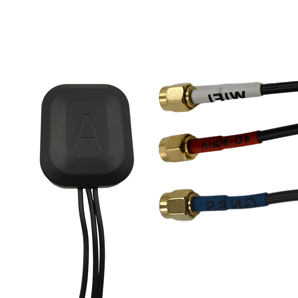
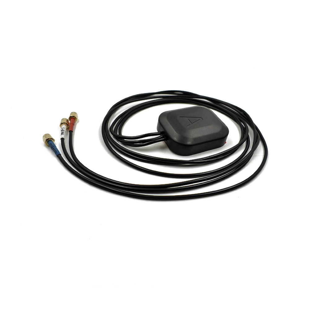
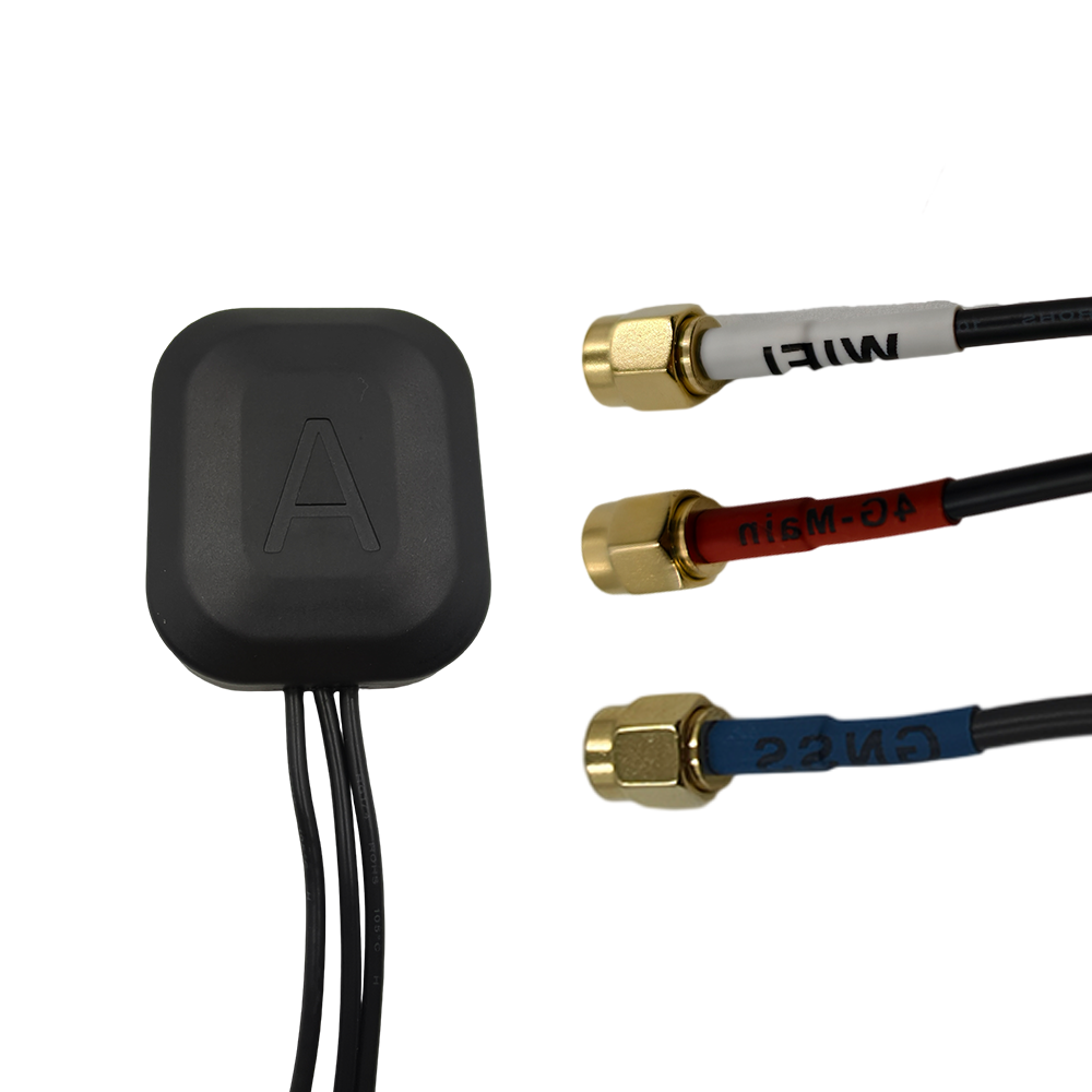
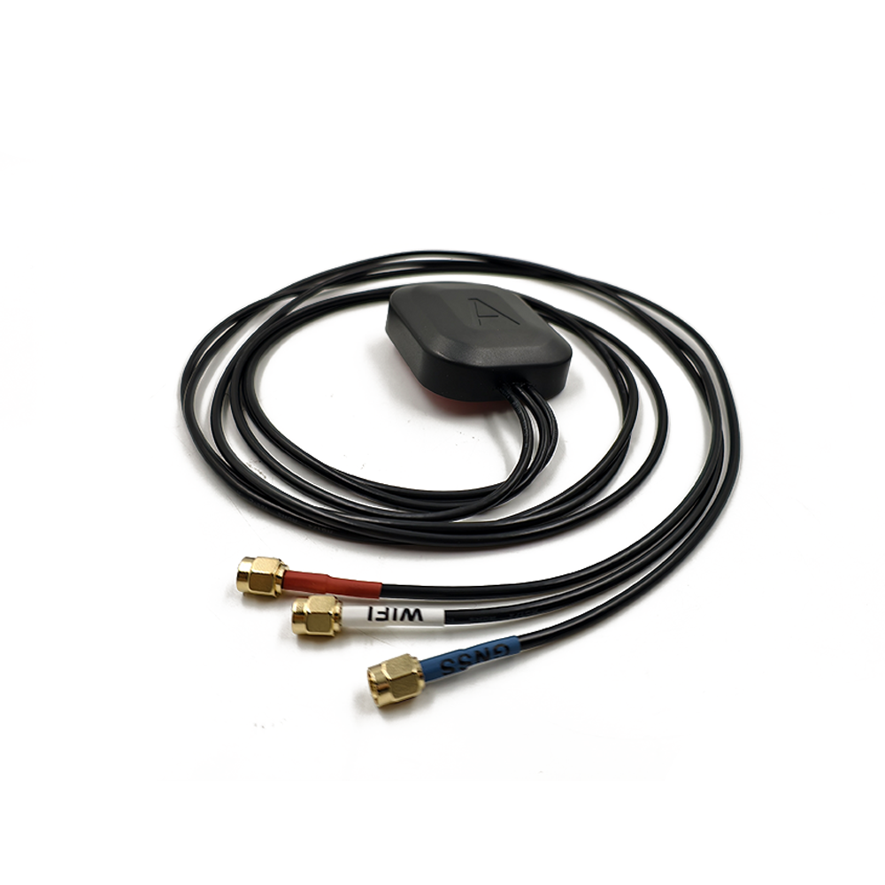
The Global Navigation Satellite System (GNSS) has revolutionized positioning, navigation, and timing (PNT) applications across industries, from precision agriculture and surveying to autonomous vehicles and geospatial mapping. Within this ecosystem, Real-Time Kinematic (RTK) technology stands out for its ability to deliver centimeter-level positioning accuracy in real time, a capability that relies heavily on the performance of the RTK antenna. Among the various RTK antenna options available, the 30dB high gain RTK antenna has emerged as a critical component for scenarios where signal strength, reliability, and precision are non-negotiable. This overview aims to define the 30dB high gain RTK antenna, contextualize its role in GNSS-RTK systems, and highlight its significance in addressing modern positioning challenges.
First, it is essential to break down the key terms that define this antenna type. “RTK” refers to Real-Time Kinematic technology, which enhances GNSS accuracy by using a base station and a rover (the device with the antenna) to correct for errors in satellite signals. These errors, caused by factors like ionospheric delays, tropospheric interference, and multipath (signal reflection off surfaces), can otherwise reduce positioning accuracy to meters. RTK mitigates these issues by transmitting correction data from the base station to the rover in real time, but this process depends entirely on the rover’s antenna’s ability to receive both satellite signals and correction data clearly.
The “30dB high gain” specification is another critical element. Gain, measured in decibels (dB), quantifies an antenna’s ability to focus or amplify signal strength in a specific direction compared to an isotropic antenna (a theoretical antenna that radiates equally in all directions). A 30dB gain indicates a significant amplification capability—far higher than standard RTK antennas, which typically range from 15dB to 25dB. This high gain means the antenna can capture weaker satellite signals, extend the effective range of the RTK system, and maintain performance in environments where signal obstruction or interference is common, such as urban canyons, dense forests, or remote rural areas.
To understand the importance of the 30dB high gain RTK antenna, it is helpful to contrast it with lower-gain alternatives. In ideal conditions—open skies with minimal interference—a standard 20dB RTK antenna may perform adequately, delivering centimeter-level accuracy within a few kilometers of the base station. However, in real-world scenarios, challenges arise. For example, in precision agriculture, a farmer using an RTK-guided tractor may need to operate in fields surrounded by tall crops or near tree lines, which block or weaken satellite signals. A 30dB high gain antenna, with its enhanced signal amplification, can penetrate these obstructions more effectively, ensuring the tractor maintains accurate positioning to avoid over- or under-fertilizing. Similarly, in construction surveying in urban areas, where buildings reflect and block signals (multipath interference), the high gain helps the antenna prioritize direct satellite signals over reflected ones, reducing errors.
Another key context for the 30dB high gain RTK antenna is the evolution of GNSS itself. With the expansion of systems like GPS (United States), Galileo (European Union), GLONASS (Russia), and BeiDou (China), modern RTK systems can access more satellites, improving redundancy and accuracy. However, this increased satellite availability also means antennas must handle more signals simultaneously while filtering out noise. The 30dB gain, combined with advanced signal processing technologies, allows the antenna to efficiently capture signals from multiple constellations, even when those signals are weak, further enhancing reliability.
Additionally, the rise of autonomous systems—such as self-driving cars, drones for delivery or inspection, and robotic surveyors—has raised the bar for RTK performance. These systems require continuous, high-precision positioning to operate safely; a momentary loss of signal or a drop in accuracy could lead to accidents or costly errors. The 30dB high gain RTK antenna addresses this need by providing a more robust signal link. For instance, a drone inspecting power lines in a mountainous region may encounter variable terrain and weather conditions (e.g., fog, rain), which weaken signals. The high gain ensures the drone remains connected to the RTK base station and GNSS satellites, allowing it to navigate precisely along the power line route.
It is also important to note that the 30dB high gain RTK antenna is not a “one-size-fits-all” solution, but rather a specialized tool for specific use cases. Its high gain comes with trade-offs, such as a narrower beamwidth (the direction in which the antenna radiates and receives signals). A narrower beamwidth means the antenna must be more precisely aligned with satellites, which may require additional mechanical or electronic steering mechanisms in some applications. However, for scenarios where long-range operation or signal penetration is critical, the benefits of high gain far outweigh these trade-offs.
In summary, the 30dB high gain RTK antenna is a specialized component that bridges the gap between theoretical RTK accuracy and real-world performance. By amplifying weak signals, resisting interference, and extending the range of RTK systems, it enables centimeter-level positioning in challenging environments that would otherwise limit the utility of standard RTK antennas. As industries continue to demand higher precision, reliability, and flexibility in PNT applications, the 30dB high gain RTK antenna is poised to play an increasingly vital role in advancing GNSS-RTK technology.
The performance of a 30dB high gain RTK antenna—its ability to amplify signals, resist interference, and maintain centimeter-level accuracy—stems directly from its design and construction. Unlike standard RTK antennas, which prioritize simplicity and cost-effectiveness, the 30dB high gain variant requires meticulous engineering to achieve its high gain while addressing trade-offs like beamwidth and signal integrity. This section breaks down the key design principles, components, materials, and manufacturing processes that define the 30dB high gain RTK antenna, highlighting how each element contributes to its overall functionality.
2.1 Core Design Principles
The primary goal of designing a 30dB high gain RTK antenna is to maximize signal amplification in the direction of GNSS satellites while minimizing noise and interference. To achieve this, engineers adhere to several core principles:
2.1.1 Beamforming and Directivity
Gain and directivity are closely linked: higher directivity (focusing signals in a specific direction) leads to higher gain. For a 30dB gain antenna, this means designing a narrow beamwidth—typically between 30 and 60 degrees in the vertical plane (elevation) and 120 to 180 degrees in the horizontal plane (azimuth). This narrow beam allows the antenna to concentrate its energy on capturing signals from overhead satellites, reducing the impact of signals from low angles (which are more prone to multipath interference) and noise from the horizon.
To achieve this directivity, engineers often use array antenna designs rather than single-element antennas. An array consists of multiple radiating elements (e.g., patch antennas) arranged in a specific pattern (e.g., circular, rectangular) and connected to a feed network. By adjusting the phase and amplitude of the signal sent to each element (a process called beamforming), the array can focus its reception pattern on satellites, effectively boosting gain to 30dB. For example, a 4x4 patch array (16 elements) can achieve significantly higher gain than a single patch element, as each element contributes to the overall signal amplification.
2.1.2 Frequency Band Optimization
GNSS systems operate across multiple frequency bands: GPS uses L1 (1575.42 MHz) and L2 (1227.60 MHz); Galileo uses E1 (1575.42 MHz) and E5 (1176.45 MHz); BeiDou uses B1 (1561.098 MHz) and B2 (1207.14 MHz); and GLONASS uses G1 (1602 MHz) and G2 (1246 MHz). A 30dB high gain RTK antenna must be designed to operate across these bands to access multiple constellations, improving redundancy and accuracy.
This requires wideband or multi-band radiating elements. Patch antennas are commonly used here because they can be designed to cover multiple bands by adjusting their size, shape, and feed position. For example, a dual-band patch element may have a larger patch for lower frequencies (e.g., L2, B2) and a smaller patch or slot for higher frequencies (e.g., L1, B1). The feed network is also optimized to distribute signals evenly across bands, ensuring that gain remains consistent (around 30dB) across all relevant frequencies.
2.1.3 Noise Reduction and Interference Mitigation
High gain can amplify not just desired satellite signals but also noise and interference (e.g., from cellular towers, Wi-Fi routers, or other electronic devices). To address this, the antenna design incorporates filtering and shielding mechanisms.
Band-pass filters: These are integrated into the feed network to block signals outside the GNSS frequency bands. For example, a filter for the L1 band would allow only signals around 1575.42 MHz to pass through, rejecting cellular signals (e.g., 1800 MHz for 4G) or Wi-Fi signals (2.4 GHz or 5 GHz).
Ground planes: A large, conductive ground plane (typically made of aluminum or copper) is placed beneath the radiating elements. This ground plane reflects unwanted signals away from the elements and reduces radiation from the antenna’s backside (backlobe), which can pick up noise from the ground or nearby objects.
Chassis shielding: The antenna’s outer housing (chassis) is often made of conductive materials (e.g., stainless steel) or lined with electromagnetic interference (EMI) shielding foam. This prevents external EMI from penetrating the antenna and disrupting signal reception.
2.2 Key Components
The 30dB high gain RTK antenna consists of several critical components, each with a specific role in achieving high performance:
2.2.1 Radiating Elements
As mentioned, patch antennas are the most common radiating elements for 30dB high gain RTK antennas. They are compact, lightweight, and easy to manufacture in arrays. Each patch is a flat, conductive sheet (usually copper) mounted on a dielectric substrate (e.g., FR4, a glass-reinforced epoxy resin with a dielectric constant of ~4.4). The size of the patch determines its resonant frequency: larger patches resonate at lower frequencies, while smaller patches resonate at higher frequencies. For multi-band operation, patches may be stacked (one on top of another) or have slots cut into them to cover multiple frequencies.
2.2.2 Feed Network
The feed network is responsible for delivering power to the radiating elements (in transmission) and collecting signals from them (in reception). For array antennas, the feed network must distribute signals with precise phase and amplitude to enable beamforming. Common feed network designs for 30dB gain antennas include series-fed arrays and parallel-fed arrays:
Series-fed arrays: Elements are connected in a chain, with signal passing from one element to the next. This design is simple but can lead to uneven gain across elements if not optimized.
Parallel-fed arrays: Each element is connected directly to a central feed point via a transmission line (e.g., microstrip line). This allows for more precise control of phase and amplitude, making it ideal for high-gain arrays.
The feed network also includes phase shifters and attenuators to adjust the signal characteristics of each element. For example, a phase shifter can delay the signal to a specific element, steering the antenna’s beam toward a satellite that is not directly overhead.
2.2.3 Low-Noise Amplifier (LNA)
While the antenna array provides most of the 30dB gain, a low-noise amplifier (LNA) is integrated into the design to further boost the signal before it is sent to the RTK receiver. The LNA is critical because it amplifies the weak satellite signal (which may be as low as -160 dBm) without adding significant noise. A high-performance LNA has a noise figure (NF) of less than 1 dB, ensuring that the signal-to-noise ratio (SNR) remains high. The LNA is typically placed close to the radiating elements to minimize signal loss in the transmission line between the antenna and the receiver.
2.2.4 Housing and Mounting
The antenna’s housing protects the internal components from environmental factors like rain, dust, temperature extremes, and physical damage. For outdoor applications (e.g., agriculture, construction), the housing is rated to IP67 or IP68 standards, meaning it is fully waterproof and dust-tight. The housing material is often a durable plastic (e.g., polycarbonate) or composite material that is lightweight but strong.
Mounting hardware is also part of the design, as the antenna must be securely attached to a vehicle (e.g., tractor, drone), a survey pole, or a fixed structure (e.g., base station). The mount may include a tilt adjustment to align the antenna’s beam with the satellite constellation, especially in applications where the antenna is not mounted on a level surface.
2.3 Materials Selection
The choice of materials directly impacts the antenna’s performance, durability, and cost. Key materials include:
2.3.1 Dielectric Substrate
The substrate for patch elements must have a stable dielectric constant (εr) to ensure consistent frequency performance. FR4 is a common choice for low-cost applications, but for higher performance, materials like Rogers 4350 (εr = 3.48) or Taconic TLY-5 (εr = 2.2) are used. These materials have lower loss tangent (tanδ), meaning they absorb less signal energy, improving the antenna’s efficiency.
2.3.2 Conductive Materials
Copper is the primary material for radiating elements and ground planes because of its high electrical conductivity (58 S/m) and low cost. For applications requiring higher durability (e.g., marine environments), gold plating may be applied to the copper to prevent corrosion. The feed network’s transmission lines are also made of copper, often etched onto the dielectric substrate using photolithography.
2.3.3 Shielding Materials
EMI shielding materials include conductive foams (e.g., nickel-coated polyurethane foam) and metal sheets (e.g., aluminum, stainless steel). These materials block external interference by absorbing or reflecting electromagnetic waves. The housing may also include a ferrite bead or choke to suppress common-mode noise in the power and signal cables.
2.4 Manufacturing Processes
The manufacturing of a 30dB high gain RTK antenna is a precision process that involves several steps:
2.4.1 Fabrication of Radiating Elements and Feed Network
The radiating elements (patches) and feed network are fabricated using printed circuit board (PCB) technology. First, a dielectric substrate is coated with a thin layer of copper. A photomask (a stencil of the desired pattern) is then placed over the copper layer, and the assembly is exposed to ultraviolet (UV) light. The unexposed copper is etched away using a chemical solution, leaving behind the patch elements and transmission lines. This process ensures high precision—critical for maintaining the correct frequency response and phase alignment in the array.
2.4.2 Assembly of Components
Once the PCB is fabricated, the LNA, filters, and other electronic components are soldered onto the board using surface-mount technology (SMT). The radiating array is then attached to the ground plane, and the entire assembly is placed inside the housing. The housing is sealed using gaskets or adhesive to ensure water and dust resistance.
2.4.3 Testing and Calibration
Testing is a critical step to ensure the antenna meets the 30dB gain specification and other performance metrics (e.g., beamwidth, frequency coverage, noise figure). Key tests include:
Gain measurement: Using an anechoic chamber (a room designed to absorb electromagnetic waves), engineers measure the antenna’s gain across all relevant frequencies. The antenna is placed on a turntable, and a signal generator and receiver are used to measure the signal strength at different angles.
Beam pattern measurement: This test maps the antenna’s reception pattern, verifying that the beam is narrow and focused on the sky.
Noise figure measurement: The LNA’s noise figure is measured using a noise figure analyzer to ensure it is below 1 dB.
Environmental testing: The antenna is subjected to temperature cycles (-40°C to 85°C), humidity, vibration, and water immersion to ensure it performs reliably in harsh conditions.
After testing, the antenna may be calibrated to adjust the feed network’s phase and amplitude settings, optimizing gain and beamforming performance for specific applications.
In conclusion, the design and construction of a 30dB high gain RTK antenna is a complex process that integrates array design, frequency optimization, noise reduction, and precision manufacturing. Each component and material is carefully selected to achieve the high gain, wide frequency coverage, and environmental durability required for demanding RTK applications. By adhering to these design principles and manufacturing standards, engineers can create antennas that deliver the centimeter-level accuracy and reliability needed in modern PNT systems.
To appreciate the value of a 30dB high gain RTK antenna, it is essential to understand how it operates within a Real-Time Kinematic (RTK) system and how its high gain enhances the overall positioning process. Unlike standalone GNSS antennas, which simply receive satellite signals, the 30dB high gain RTK antenna works in tandem with a base station, a rover receiver, and advanced signal processing algorithms to deliver centimeter-level accuracy. This section breaks down the working principles of the antenna, from signal reception and amplification to its role in RTK error correction, highlighting how the 30dB gain addresses key challenges in signal acquisition and processing.
3.1 The Role of the Antenna in the RTK Ecosystem
First, it is critical to contextualize the antenna within the broader RTK system. An RTK system consists of three core components:
Base Station: A fixed-position receiver with a known, precisely surveyed coordinate. The base station’s antenna (often a high-stability, fixed-gain antenna) continuously receives GNSS signals and calculates its own “measured” position. Since the base station’s true position is known, it can determine the error vector—the difference between its measured position and true position. This error vector accounts for common GNSS errors (ionospheric delay, tropospheric interference, satellite clock drift) that affect all receivers in the same geographic area.
Rover: A mobile receiver (e.g., mounted on a tractor, drone, or survey pole) that uses the 30dB high gain RTK antenna to receive GNSS signals. The rover’s goal is to calculate its real-time position with centimeter-level accuracy.
Data Link: A communication channel (e.g., radio, cellular, or satellite) that transmits the base station’s error correction data to the rover.
The 30dB high gain RTK antenna is the rover’s “ears” in this system. Its primary role is twofold: (1) receive weak or obstructed GNSS signals from multiple satellites across different constellations (GPS, Galileo, etc.), and (2) receive the base station’s correction data via the data link. Without a high-gain antenna, the rover may struggle to capture either signal type in challenging environments, leading to lost connections or reduced accuracy.
For example, consider a base station located 10 km from a rover operating in a dense forest. The base station’s correction data is transmitted via a low-power radio link (common in RTK systems for cost and simplicity). A standard 20dB antenna on the rover may not have enough gain to detect this weak radio signal, leading to a loss of correction data. In contrast, the 30dB high gain antenna amplifies the radio signal, ensuring the rover receives the correction data reliably. At the same time, it amplifies the weak GNSS signals that penetrate the forest canopy, allowing the rover to track enough satellites to calculate a position.
3.2 Signal Reception and Amplification: How 30dB Gain Works
The core function of the 30dB high gain RTK antenna is to receive and amplify two types of signals: GNSS satellite signals and base station correction data. To understand how the 30dB gain enhances this process, we need to break down the signal path from transmission to reception.
3.2.1 GNSS Satellite Signal Reception
GNSS satellites transmit signals at extremely low power levels—by the time a signal reaches Earth’s surface, its power is typically between -150 dBm and -160 dBm (equivalent to a few trillionths of a watt). This makes the signal highly susceptible to attenuation (weakening) from obstacles like buildings, trees, or atmospheric gases. The 30dB high gain antenna addresses this by focusing its reception pattern on the sky (via its narrow beamwidth) and amplifying the signal as it is captured.
The amplification process begins with the radiating array (e.g., a 4x4 patch array). Each patch element in the array captures a small portion of the GNSS signal. The feed network then combines these signals, adjusting their phase and amplitude to reinforce each other (constructive interference) in the direction of the satellite. This combination, along with the array’s directivity, provides the majority of the 30dB gain.
Next, the amplified signal is sent to the low-noise amplifier (LNA). The LNA boosts the signal by an additional 10–15 dB (depending on the design) while adding minimal noise. This is critical because the signal is still very weak after the array—adding noise here would reduce the signal-to-noise ratio (SNR), making it harder for the receiver to process the signal. A high-performance LNA (with a noise figure <1 dB) ensures that the SNR remains high, even after amplification.
Finally, the signal passes through band-pass filters to remove any interference from frequencies outside the GNSS bands. For example, a filter for the L1 band (1575.42 MHz) blocks signals from nearby cellular towers (e.g., 1800 MHz for 4G) or Wi-Fi routers (2.4 GHz). This filtered, amplified signal is then sent to the rover’s RTK receiver for processing.
To quantify the impact of 30dB gain: A GNSS signal with a power of -160 dBm at the antenna’s input is amplified to -130 dBm at the output (a 1,000x increase in power). This makes the signal strong enough for the receiver to decode the satellite’s ephemeris data (orbital information) and pseudorange measurements (distance from the satellite to the rover).
3.2.2 Base Station Correction Data Reception
The base station’s correction data is typically transmitted via a radio link (e.g., UHF or VHF bands) or a cellular network (e.g., 4G LTE). These signals are also often weak, especially at long ranges or in areas with poor coverage. The 30dB high gain antenna’s ability to amplify these signals is just as critical as its amplification of GNSS signals.
In radio-based RTK systems, the base station uses a low-power transmitter (e.g., 1 W) to send correction data. At a range of 15 km, the signal power at the rover’s antenna may be as low as -110 dBm. A standard 20dB antenna would amplify this to -90 dBm, which may be too weak for the rover’s receiver to detect. The 30dB antenna amplifies it to -80 dBm, a 10x increase in power compared to the 20dB antenna, ensuring reliable reception.
For cellular-based RTK systems (common in urban areas where radio links are blocked by buildings), the 30dB gain helps the antenna capture weak 4G/5G signals. This is particularly important in urban canyons, where tall buildings reflect and block cellular signals. The antenna’s narrow beamwidth allows it to focus on the nearest cell tower, reducing interference from other towers and amplifying the weak signal enough for the rover to receive the correction data.
3.3 Error Correction: The Antenna’s Role in RTK Accuracy
RTK accuracy relies on the rover’s ability to combine its own GNSS measurements with the base station’s correction data. The 30dB high gain antenna plays a critical role in this process by ensuring both types of data are accurate and reliable.
3.3.1 Reducing Multipath Error
Multipath interference is one of the most significant sources of error in GNSS positioning. It occurs when a GNSS signal reflects off a surface (e.g., a building, road, or water) before reaching the antenna, creating a “ghost” signal that the receiver mistakes for the direct signal. This leads to incorrect pseudorange measurements, which can reduce accuracy to meters.
The 30dB high gain antenna mitigates multipath in two ways:
Narrow Beamwidth: The antenna’s narrow elevation beamwidth (30–60 degrees) means it primarily receives signals from high-angle satellites (above 30 degrees elevation). Low-angle satellites (below 30 degrees) are more prone to multipath because their signals travel a longer path through the atmosphere and are more likely to reflect off surfaces. By focusing on high-angle satellites, the antenna reduces the number of multipath signals it captures.
High SNR: The 30dB gain increases the SNR of the direct GNSS signal relative to the multipath signal. For example, if a direct signal has a power of -160 dBm and a multipath signal has a power of -165 dBm, the 30dB gain amplifies both to -130 dBm and -135 dBm, respectively. The receiver can then use signal processing algorithms to distinguish the stronger direct signal from the weaker multipath signal, reducing measurement errors.
3.3.2 Enabling Multi-Constellation Tracking
Modern RTK systems rely on tracking multiple GNSS constellations (GPS, Galileo, BeiDou, GLONASS) to improve redundancy and accuracy. The more satellites the rover can track, the more reliable its position calculation—if one satellite’s signal is lost (e.g., due to obstruction), the rover can use signals from other satellites to maintain accuracy.
The 30dB high gain antenna enables multi-constellation tracking by amplifying weak signals from less powerful satellites (e.g., Galileo satellites, which have lower transmission power than GPS). For example, a Galileo satellite signal may be 5–10 dB weaker than a GPS signal at the rover’s location. A standard 20dB antenna may not have enough gain to detect this weak signal, leaving the rover with only GPS satellites to track. The 30dB antenna amplifies the Galileo signal enough for the receiver to track it, increasing the number of satellites and improving accuracy.
3.3.3 Maintaining Correction Data Integrity
The base station’s correction data is only useful if it is received in real time and without errors. A loss of correction data (due to a weak signal) forces the rover to switch to “float” mode, where it uses only its own GNSS measurements. In float mode, accuracy drops to 1–5 meters—far below the centimeter-level accuracy required for most RTK applications.
The 30dB high gain antenna ensures the rover receives correction data continuously by:
Amplifying weak radio or cellular signals (as discussed in Section 3.2.2), reducing the risk of signal loss.
Filtering out interference from other devices (e.g., Wi-Fi, Bluetooth) that could corrupt the correction data. The antenna’s band-pass filters block signals outside the data link’s frequency band, ensuring the correction data is received intact.
For example, in precision agriculture, a rover on a tractor needs continuous correction data to maintain a straight path while planting seeds. A 30dB high gain antenna ensures the rover receives the base station’s correction data even when the tractor is near tree lines (which block radio signals) or in low-lying areas (which weaken cellular signals). This continuous data link allows the tractor to plant seeds with centimeter-level accuracy, reducing seed waste and improving crop yields.
3.4 Beam Steering: Adapting to Dynamic Environments
While the 30dB high gain antenna has a narrow beamwidth, many modern designs include beam steering capabilities to adapt to dynamic environments (e.g., a drone flying over uneven terrain or a tractor moving through a field with tall crops). Beam steering allows the antenna to adjust its reception pattern to track satellites as the rover moves, ensuring it maintains high gain and signal strength.
Beam steering is typically achieved using electronic phase shifters in the feed network. The phase shifters adjust the phase of the signal sent to each element in the radiating array, changing the direction of the antenna’s beam. For example, if the rover tilts 15 degrees to the left (e.g., a drone banking during a turn), the phase shifters can adjust the phase of the left-side elements to steer the beam 15 degrees to the right, keeping it focused on the satellites.
This capability is critical for mobile rovers. Without beam steering, the narrow beamwidth of the 30dB antenna could cause it to lose satellite signals as the rover tilts or moves. For example, a drone flying at a 30-degree angle would have its antenna’s beam pointing 30 degrees away from the sky, leading to a loss of GNSS signals. Beam steering corrects this, ensuring the drone maintains its centimeter-level accuracy even during dynamic maneuvers.
In summary, the 30dB high gain RTK antenna’s working principles revolve around three core functions: receiving and amplifying weak GNSS and correction signals, mitigating interference and multipath errors, and enabling reliable multi-constellation tracking. By focusing its reception pattern, amplifying signals without adding noise, and adapting to dynamic environments via beam steering, the antenna ensures the rover can deliver centimeter-level accuracy in even the most challenging conditions. It is not just a “signal booster”—it is an integral part of the RTK system’s ability to translate theoretical accuracy into real-world performance.
The 30dB high gain RTK antenna has become a go-to solution for industries requiring high-precision positioning in challenging environments, but like any technology, it comes with distinct advantages and inherent challenges. Understanding these trade-offs is critical for engineers, system integrators, and end-users to determine whether the antenna is the right fit for their application. This section explores the key advantages of the 30dB high gain RTK antenna, as well as the challenges it presents, along with strategies to mitigate those challenges.
4.1 Key Advantages
The 30dB high gain RTK antenna’s primary advantages stem from its ability to amplify weak signals, resist interference, and extend the capabilities of RTK systems. These benefits make it indispensable in applications where standard RTK antennas fall short.
4.1.1 Extended RTK System Range
One of the most significant advantages of the 30dB high gain antenna is its ability to extend the effective range of RTK systems. The range of an RTK system is typically limited by the rover’s ability to receive the base station’s correction data and track enough GNSS satellites. A standard 20dB antenna may limit the range to 5–10 km in open areas and 1–3 km in obstructed areas (e.g., forests, urban canyons). The 30dB antenna, with its higher gain, can extend this range to 15–25 km in open areas and 5–10 km in obstructed areas.
This extended range has practical benefits for large-scale applications. For example, in precision agriculture, a single base station can cover a 5,000-acre farm (instead of 2,000 acres with a standard antenna), reducing the number of base stations needed and lowering costs. In surveying, a survey team can cover a larger construction site without relocating the base station, saving time and improving efficiency.
4.1.2 Improved Performance in Challenging Environments
The 30dB high gain antenna excels in environments where signal obstruction or interference is common. These include:
Urban Canyons: Tall buildings block GNSS signals and reflect cellular/radio signals, making it hard for standard antennas to track satellites or receive correction data. The 30dB gain amplifies weak signals, while the narrow beamwidth focuses on direct satellite and cell tower signals, reducing multipath and interference.
Dense Forests: Tree canopies attenuate GNSS signals by 10–20 dB, making them too weak for standard antennas to detect. The 30dB gain compensates for this attenuation, allowing the rover to track satellites through the canopy.
Remote Rural Areas: Base stations are often sparse in rural areas, leading to weak correction data signals. The 30dB antenna amplifies these signals, ensuring the rover receives correction data even at long distances from the base station.
For example, a drone used for power line inspection in a mountainous forest may encounter fog, rain, and thick tree cover—all of which weaken GNSS and radio signals. A standard antenna would likely lose signal, forcing the drone to land. The 30dB high gain antenna, however, amplifies the weak signals, allowing the drone to complete the inspection without interruption.
4.1.3 Higher Positioning Accuracy and Reliability
The 30dB high gain antenna directly improves RTK accuracy and reliability by:
Increasing SNR: A higher SNR means the receiver can decode satellite signals more accurately, reducing pseudorange measurement errors. This leads to more precise position calculations—often within 1–2 cm, compared to 3–5 cm with a standard antenna.
Enabling Multi-Constellation Tracking: As discussed in Section 3.3.2, the 30dB gain allows the antenna to track weak signals from less powerful satellites (e.g., Galileo, BeiDou). Tracking more satellites improves redundancy—if one satellite’s signal is lost, the rover can use others to maintain accuracy.
Reducing Signal Dropouts: The antenna’s ability to amplify weak signals reduces the risk of losing GNSS or correction data. In applications like autonomous driving, where signal dropouts can cause accidents, this reliability is critical.
For instance, in construction surveying, where precise positioning is needed to lay foundation walls or install structural beams, a 30dB high gain antenna ensures the surveyor’s rover maintains 1 cm accuracy even near tall buildings or heavy machinery (which emits EMI). This reduces rework and ensures the project adheres to design specifications.
4.1.4 Compatibility with Low-Power Base Stations
Many RTK systems use low-power base stations (1–5 W) to reduce cost, size, and power consumption. These base stations transmit correction data at lower power levels, making their signals harder to detect at long ranges. The 30dB high gain antenna’s ability to amplify weak signals makes it compatible with these low-power base stations, allowing users to deploy RTK systems in remote areas without access to grid power (e.g., using solar-powered base stations).
This compatibility is particularly valuable in industries like mining or oil and gas, where operations often take place in remote locations with limited infrastructure. For example, a mining company may need to track the position of haul trucks in a remote mine site. Using a solar-powered low-power base station (2 W) and a 30dB high gain antenna on the trucks allows the company to deploy an RTK system without running power lines to the base station. The antenna amplifies the base station’s weak correction signals, ensuring the trucks’ positions are tracked with centimeter-level accuracy—critical for optimizing haul routes and preventing collisions.
4.2 Key Challenges and Mitigation Strategies
While the 30dB high gain RTK antenna offers significant advantages, it also presents challenges that must be addressed to maximize its performance. These challenges are primarily tied to its high gain and narrow beamwidth, which can limit flexibility in certain applications. Below are the most common challenges, along with practical strategies to mitigate them.
4.2.1 Narrow Beamwidth and Limited Angular Coverage
The 30dB high gain antenna’s narrow beamwidth (30–60 degrees in elevation, 120–180 degrees in azimuth) is a double-edged sword: it enables high gain by focusing on specific directions, but it also limits the antenna’s ability to track satellites outside this narrow range. For example, if a rover is in an area where most satellites are at low elevations (e.g., near the poles, where satellite orbits are lower relative to the horizon), the antenna may struggle to track enough satellites to calculate a position.
Mitigation Strategies:
Dual-Beam or Multi-Beam Designs: Some modern 30dB high gain antennas use dual-beam or multi-beam arrays to expand angular coverage. A dual-beam antenna, for instance, has two overlapping beams—one for high-elevation satellites (30–60 degrees) and one for medium-elevation satellites (15–30 degrees). This allows the antenna to track more satellites while maintaining high gain in each beam.
Electronic Beam Steering with Wide Azimuth Coverage: As discussed in Section 3.4, electronic beam steering can adjust the antenna’s beam direction. To address narrow azimuth coverage, some antennas use a circular array of elements, which provides 360-degree azimuth coverage. The beam steering system can then focus the beam on satellites in any horizontal direction, while maintaining a narrow elevation beamwidth for high gain.
Antenna Tilt Adjustment for Fixed Applications: For fixed rovers (e.g., a survey pole mounted on a tripod), manual or motorized tilt adjustment can align the antenna’s beam with the satellite constellation. For example, in polar regions, tilting the antenna 15–20 degrees toward the horizon can help it track low-elevation satellites without sacrificing too much gain.
4.2.2 Sensitivity to Misalignment
The 30dB high gain antenna’s narrow beamwidth makes it highly sensitive to misalignment. Even a small tilt (5–10 degrees) can cause the beam to shift away from satellites, leading to signal loss or reduced gain. This is a significant challenge for mobile rovers that experience vibration or movement (e.g., a drone flying through turbulence or a tractor bouncing over rough terrain).
Mitigation Strategies:
Integrated Inertial Measurement Units (IMUs): Many modern 30dB high gain antennas include an IMU, which measures the antenna’s orientation (tilt, roll, yaw) in real time. The IMU data is sent to the beam steering system, which adjusts the beam direction to compensate for misalignment. For example, if a drone tilts 10 degrees to the right, the IMU detects the tilt, and the beam steering system shifts the beam 10 degrees to the left, keeping it focused on satellites.
Shock and Vibration Dampening: The antenna’s housing and mounting hardware can be designed with shock absorbers or vibration dampeners (e.g., rubber gaskets, spring-loaded mounts) to reduce the impact of movement. For example, a tractor-mounted antenna may use a heavy-duty mount with rubber bushings to absorb vibrations from the tractor’s engine and rough terrain, preventing misalignment.
Auto-Calibration for Fixed Rovers: For fixed rovers (e.g., base stations or survey poles), auto-calibration software can detect misalignment and adjust the antenna’s settings. The software compares the antenna’s measured position to its true position (from a known survey point) and calculates the misalignment angle. It then sends a signal to the beam steering system to correct the beam direction.
4.2.3 Higher Power Consumption
The 30dB high gain antenna’s components—including the radiating array, LNA, and beam steering system—consume more power than standard RTK antennas. A standard 20dB antenna may consume 5–10 watts (W) of power, while a 30dB high gain antenna with beam steering can consume 15–25 W. This is a challenge for battery-powered rovers (e.g., drones, portable survey devices), where power life is critical.
Mitigation Strategies:
Low-Power Component Design: Manufacturers can use low-power LNAs and phase shifters to reduce power consumption. For example, a low-power LNA may consume 2–3 W instead of 5–6 W, while maintaining a noise figure of <1 dB. Similarly, digital phase shifters (which use less power than analog phase shifters) can reduce the beam steering system’s power consumption by 30–40%.
Power Management Systems: The antenna can be integrated with a power management system that adjusts power consumption based on demand. For example, when the rover is in an open area with strong satellite signals, the system can reduce the LNA’s gain or turn off unused beam steering channels, lowering power consumption. When the rover enters an obstructed area, the system increases power to maintain high gain.
Battery Optimization for Mobile Rovers: For battery-powered rovers, the antenna’s power consumption can be balanced with other components (e.g., the receiver, data link) to extend battery life. For example, a drone may use a high-capacity lithium-ion battery (5000 mAh) and optimize the antenna’s power usage to ensure it can fly for 30–40 minutes—enough time to complete a typical inspection mission.
4.2.4 Higher Cost and Complexity
The 30dB high gain RTK antenna is more expensive and complex to manufacture than standard RTK antennas. The radiating array, LNA, beam steering system, and filtering components add to the cost— a 30dB high gain antenna may cost \(500–\)1500, compared to \(200–\)500 for a standard 20dB antenna. Additionally, the complexity of the design requires specialized engineering and testing, which further increases costs.
Mitigation Strategies:
Scalable Designs for Mass Production: Manufacturers can design the antenna with scalable components (e.g., modular patch arrays) that reduce production costs when manufactured in large quantities. For example, a modular array allows manufacturers to use the same base design for different gain levels (25dB, 30dB, 35dB) by adding or removing patch elements, reducing the need for separate tooling and testing.
Targeted Pricing for High-Value Applications: The higher cost of the 30dB high gain antenna is often justified in high-value applications where accuracy and reliability are critical (e.g., autonomous driving, precision surgery). Manufacturers can target these markets with premium pricing, while offering lower-cost versions (e.g., without beam steering) for less demanding applications (e.g., basic surveying).
Integration with RTK Receivers: Some manufacturers integrate the 30dB high gain antenna with the RTK receiver into a single unit, reducing system cost and complexity. For example, a combined antenna-receiver unit may cost \(800–\)2000, compared to \(1000–\)2500 for a separate antenna and receiver. This integration also simplifies installation and calibration, reducing labor costs for end-users.
4.2.5 Interference from Strong Local Signals
While the 30dB high gain antenna is designed to filter out interference, it can still be affected by strong local signals (e.g., a high-power radio transmitter near a construction site or a radar system at an airport). These signals can overload the LNA, causing it to saturate (i.e., the LNA can no longer amplify the signal, leading to distortion). This can result in lost GNSS signals or incorrect correction data.
Mitigation Strategies:
High-Linearity LNAs: Using a high-linearity LNA can reduce the risk of saturation. Linearity refers to the LNA’s ability to amplify signals without distortion, even when strong interference is present. A high-linearity LNA has a higher third-order intercept point (IP3), which is a measure of its ability to handle strong signals. For example, an LNA with an IP3 of +10 dBm can handle stronger interference than an LNA with an IP3 of 0 dBm.
Adaptive Filtering: Some 30dB high gain antennas use adaptive filtering, which dynamically adjusts the filter’s frequency range to block strong local signals. The antenna’s receiver detects the frequency of the interfering signal and adjusts the band-pass filter to exclude that frequency, while maintaining coverage of the GNSS bands. For example, if a high-power radio transmitter is operating at 1500 MHz (near the L1 band’s 1575.42 MHz), the adaptive filter can narrow the L1 band filter to 1570–1580 MHz, blocking the 1500 MHz signal.
Shielding for High-Interference Environments: In extreme cases (e.g., near radar systems), the antenna can be enclosed in a Faraday cage—a conductive enclosure that blocks electromagnetic waves. The Faraday cage is designed with small openings to allow GNSS signals to pass through, while blocking strong interference. For example, a survey team working near an airport may use a Faraday cage-enclosed antenna to avoid radar interference.
The 30dB high gain RTK antenna’s unique combination of high gain, interference resistance, and extended range has made it a critical component in a wide range of industries. As GNSS technology evolves and new applications emerge, the antenna’s role is expanding further. This section explores the key applications of the 30dB high gain RTK antenna, as well as the future trends that will shape its development.
5.1 Key Applications
The 30dB high gain RTK antenna is most valuable in applications where standard RTK antennas struggle to deliver centimeter-level accuracy—specifically, in challenging environments, large-scale operations, or applications requiring high reliability. Below are the most prominent use cases.
5.1.1 Precision Agriculture
Precision agriculture relies on RTK technology to optimize crop yields, reduce resource waste, and lower costs. Farmers use RTK-guided tractors, harvesters, and drones to perform tasks like planting, fertilizing, and spraying with centimeter-level accuracy. The 30dB high gain RTK antenna is ideal for this industry because it can operate in the challenging environments common in agriculture: dense crop canopies, tree-lined fields, and remote rural areas with sparse base stations.
Use Cases in Precision Agriculture:
Guided Tractors and Harvesters: A tractor equipped with a 30dB high gain antenna can maintain a straight path (within 1–2 cm accuracy) while planting seeds or applying fertilizer, even when operating near tall crops (e.g., corn, wheat) that block GNSS signals. The antenna’s high gain amplifies weak signals through the canopy, and its narrow beamwidth reduces multipath interference from the ground.
Drone-Based Crop Monitoring: Drones used for crop health monitoring (e.g., multispectral imaging) require precise positioning to ensure images are aligned correctly. The 30dB high gain antenna allows drones to operate over large fields (up to 25 km from the base station) and in areas with tree cover, ensuring consistent positioning accuracy. For example, a drone can fly over a 1000-acre cornfield, capturing images with 1 cm alignment accuracy, which helps farmers identify areas of stress (e.g., drought, pest infestations) more effectively.
Irrigation System Positioning: Precision irrigation systems (e.g., center pivots) use RTK to position sprinklers and ensure even water distribution. The 30dB high gain antenna ensures the irrigation system maintains accuracy even in remote areas, where base station signals are weak. This reduces water waste and ensures crops receive the right amount of moisture.
Example: A large-scale soybean farm in Iowa uses 10 RTK-guided tractors equipped with 30dB high gain antennas. The farm has a single solar-powered base station (3 W) located in the center of the 6000-acre property. The 30dB antennas allow the tractors to operate up to 20 km from the base station, covering the entire farm without additional base stations. The tractors plant soybeans with 1.5 cm accuracy, reducing seed waste by 15% compared to standard RTK antennas.
5.1.2 Autonomous Vehicles and Drones
Autonomous vehicles (e.g., self-driving cars, trucks) and drones (e.g., delivery drones, inspection drones) require continuous, high-precision positioning to operate safely. A momentary loss of signal or drop in accuracy can lead to accidents, missed deliveries, or failed inspections. The 30dB high gain RTK antenna addresses this need by providing a robust signal link, even in dynamic and obstructed environments.
Use Cases in Autonomous Vehicles and Drones:
Self-Driving Cars in Urban Areas: Urban canyons (tall buildings) block GNSS signals and cause multipath interference, making it hard for standard antennas to maintain accuracy. The 30dB high gain antenna’s narrow beamwidth focuses on direct satellite signals, while its high gain amplifies weak signals from cell towers (for cellular-based RTK). This ensures the car maintains 1–2 cm accuracy, critical for navigating busy streets and avoiding collisions.
Delivery Drones in Suburban Areas: Delivery drones often operate in suburban areas with trees, power lines, and houses that block GNSS signals. The 30dB high gain antenna allows drones to track satellites through tree cover and receive correction data from distant base stations (up to 15 km). For example, a delivery drone can fly from a warehouse to a customer’s house (10 km away) through a suburban neighborhood, maintaining 2 cm accuracy to land safely on the customer’s porch.
Industrial Drones for Inspection: Drones used for inspecting power lines, wind turbines, or oil pipelines often operate in remote or harsh environments (e.g., mountainous regions, offshore platforms). The 30dB high gain antenna amplifies weak GNSS and correction signals, allowing the drone to complete inspections without signal loss. For example, a wind turbine inspection drone can fly up to 25 km from the base station, capturing high-resolution images of the turbine blades with 1 cm accuracy, which helps detect cracks or damage early.
Example: A ride-sharing company testing self-driving cars in downtown Chicago uses 30dB high gain RTK antennas. The cars operate in an area with tall skyscrapers (urban canyons) and heavy traffic. The 30dB antennas amplify weak GPS and Galileo signals, while the beam steering system adjusts to track satellites as the car moves. The cars maintain 1.2 cm accuracy, allowing them to navigate lanes precisely and avoid pedestrians and other vehicles.
5.1.3 Construction and Surveying
Construction and surveying require precise positioning to ensure projects adhere to design specifications, reduce rework, and improve safety. Surveyors use RTK rovers to map construction sites, lay out foundation walls, and install structural components. The 30dB high gain RTK antenna is ideal for this industry because it can operate near tall buildings, heavy machinery (which emits EMI), and in large construction sites with a single base station.
Use Cases in Construction and Surveying:
Site Mapping and Layout: A surveyor using a 30dB high gain antenna can map a large construction site (e.g., a new airport or highway) with centimeter-level accuracy, even when the site is surrounded by trees or existing buildings. The antenna’s high gain amplifies weak GNSS signals, and its filtering system blocks EMI from construction machinery (e.g., cranes, bulldozers).
High-Rise Construction: When building skyscrapers, surveyors need to position structural components (e.g., steel beams, concrete slabs) with extreme accuracy. The 30dB high gain antenna allows surveyors to track satellites from the top of the building (where signals are often weak due to height) and receive correction data from a base station on the ground. This ensures components are aligned within 1 cm, preventing structural issues.
Underground Construction: For underground projects (e.g., tunnels, subway systems), the 30dB high gain antenna can be used in conjunction with a local base station inside the tunnel. The antenna’s high gain amplifies the base station’s correction signals, allowing surveyors to track the tunnel’s progress with centimeter-level accuracy. For example, a subway tunnel construction project in London uses 30dB high gain antennas to ensure the tunnel bores align correctly with existing stations, reducing the risk of costly rework.
Example: A construction company building a new stadium in Los Angeles uses 30dB high gain RTK antennas for surveying and layout. The stadium site is 50 acres, with existing buildings on three sides and heavy machinery operating on-site. The company has a single base station located in the center of the site. The 30dB antennas allow surveyors to work up to 15 km from the base station (covering the entire site) and maintain 1 cm accuracy, even near the existing buildings and machinery. This has reduced rework by 20% compared to using standard RTK antennas.
5.1.4 Geospatial Mapping and Remote Sensing
Geospatial mapping and remote Sensing
Geospatial mapping and remote sensing involve capturing detailed data about the Earth’s surface for applications like topographic mapping, environmental monitoring, and disaster response. These tasks require precise positioning to ensure data (e.g., satellite imagery, LiDAR scans) is georeferenced correctly—meaning each data point is tied to a specific latitude, longitude, and elevation. The 30dB high gain RTK antenna is critical here because it enables mapping systems to operate in remote or obstructed areas (e.g., mountain ranges, tropical rainforests) and maintain accuracy over large distances.
Use Cases in Geospatial Mapping and Remote Sensing:
LiDAR Mapping for Topography: LiDAR (Light Detection and Ranging) systems use laser pulses to create 3D maps of the Earth’s surface. A LiDAR drone or aircraft equipped with a 30dB high gain RTK antenna can georeference each laser pulse with centimeter-level accuracy, even when flying over dense forests or mountainous terrain. The antenna’s high gain amplifies weak GNSS signals through tree canopies or over long distances, ensuring the LiDAR data is aligned correctly with existing maps. For example, a LiDAR drone mapping a tropical rainforest in the Amazon can fly up to 20 km from a base station, capturing 3D data of the forest canopy with 1.5 cm accuracy. This data helps ecologists track deforestation and monitor biodiversity.
Satellite Imagery Ground Truthing: To validate the accuracy of satellite imagery (e.g., from Landsat or Sentinel), researchers use ground-based RTK rovers to collect “ground truth” data—precise coordinates of specific points (e.g., a riverbank, a forest edge). The 30dB high gain antenna allows these rovers to operate in remote areas (e.g., the Sahara Desert, the Arctic tundra) where base station signals are weak. For instance, a research team studying glacial retreat in Greenland uses 30dB high gain antennas on their RTK rovers. The rovers collect ground truth data up to 25 km from a solar-powered base station, ensuring the satellite imagery of the glaciers is calibrated correctly.
Disaster Response Mapping: After natural disasters like earthquakes or floods, emergency responders need fast, accurate maps to identify affected areas and plan relief efforts. Drones equipped with 30dB high gain RTK antennas can quickly map disaster zones, even in areas with damaged infrastructure (e.g., downed power lines, collapsed buildings) that block GNSS signals. The antenna’s high gain ensures the drone maintains positioning accuracy, allowing responders to create detailed maps of flooded areas or collapsed structures within hours. For example, after a hurricane in Florida, a drone with a 30dB high gain antenna mapped a 50-square-kilometer area, providing responders with 1 cm accuracy maps to locate trapped residents and coordinate rescue efforts.
Example: A geospatial mapping company working on a topographic survey of the Rocky Mountains uses 30dB high gain RTK antennas on their LiDAR-equipped aircraft. The aircraft flies at an altitude of 5,000 meters, covering 1,000 square kilometers per day. The 30dB antennas allow the aircraft to receive correction data from a single base station located in a valley, 20 km from the survey area. The LiDAR data is georeferenced with 1.2 cm accuracy, enabling the company to create detailed topographic maps that are used for highway construction and wildlife conservation planning.
5.2 Future Trends
As GNSS technology advances and new industry needs emerge, the 30dB high gain RTK antenna is poised to evolve in several key directions. These trends will focus on improving performance, reducing limitations, and expanding the antenna’s applicability to new use cases.
5.2.1 Integration with 5G and Next-Generation GNSS
The rollout of 5G networks and the expansion of next-generation GNSS constellations (e.g., GPS III, Galileo Second Generation, BeiDou-3) will drive significant improvements in 30dB high gain RTK antenna design.
5G-Enabled RTK: 5G networks offer higher bandwidth, lower latency, and wider coverage than 4G, making them ideal for transmitting large volumes of RTK correction data. Future 30dB high gain antennas will be integrated with 5G modems, allowing rovers to receive correction data from cloud-based RTK services (instead of local base stations). This “network RTK” approach will eliminate the need for on-site base stations, reducing costs and increasing flexibility. For example, a self-driving car with a 5G-integrated 30dB high gain antenna could receive correction data from a cloud service, enabling centimeter-level accuracy in any area with 5G coverage—even in remote regions where local base stations are unavailable.
Next-Generation GNSS Support: Next-generation GNSS constellations use new frequency bands (e.g., GPS III’s L1C band, Galileo’s E6 band) and advanced signal formats that offer higher accuracy and better resistance to interference. Future 30dB high gain antennas will be designed to support these new bands, allowing rovers to track more satellites and achieve even higher precision. For instance, an antenna that supports GPS III’s L1C band (which has a more robust signal than older bands) could maintain centimeter-level accuracy in urban canyons with fewer satellites, reducing the risk of signal loss.
5.2.2 Miniaturization and Low-Power Design
As applications like wearable devices and small drones demand smaller, more power-efficient components, 30dB high gain RTK antennas will undergo significant miniaturization while maintaining performance.
Miniaturized Arrays: Advances in microelectronics (e.g., microstrip patch technology, MEMS—Micro-Electro-Mechanical Systems) will allow manufacturers to create smaller radiating arrays. A future 30dB high gain antenna could be the size of a credit card, making it suitable for wearable devices (e.g., precision tracking devices for hikers or athletes) or small delivery drones. For example, a small delivery drone (weighing less than 2 kg) could use a miniaturized 30dB high gain antenna to maintain centimeter-level accuracy, enabling it to deliver packages to small balconies or narrow driveways.
Ultra-Low-Power Components: New materials and circuit designs will reduce the power consumption of 30dB high gain antennas. For instance, researchers are developing “energy-harvesting” LNAs that use ambient electromagnetic energy (e.g., from 5G signals) to power themselves, reducing the antenna’s reliance on batteries. This would be particularly valuable for battery-powered devices like portable survey rovers or wildlife tracking collars, which need to operate for weeks or months without recharging.
5.2.3 AI-Driven Adaptive Beam Steering and Interference Mitigation
Artificial intelligence (AI) and machine learning (ML) will play an increasingly important role in optimizing 30dB high gain RTK antenna performance, particularly in dynamic or high-interference environments.
AI-Powered Beam Steering: Current beam steering systems rely on pre-programmed algorithms to adjust the antenna’s beam direction. Future systems will use AI to learn from real-time data (e.g., satellite positions, signal strength, interference levels) and optimize beam steering dynamically. For example, an AI-driven system could predict the movement of satellites and adjust the beam direction in advance, ensuring the antenna maintains a strong signal even as the rover moves. This would be particularly useful for fast-moving rovers like autonomous trucks or racing drones.
ML-Based Interference Mitigation: ML algorithms will enable 30dB high gain antennas to detect and block new types of interference (e.g., jamming signals from malicious actors, unexpected radio signals from new devices) in real time. The algorithm would analyze the frequency, amplitude, and pattern of incoming signals, classifying them as “desired” (GNSS, correction data) or “undesired” (interference). It would then adjust the antenna’s filters or beam direction to block the interference. For instance, in a military application, an AI-equipped 30dB high gain antenna could detect and block jamming signals, ensuring the RTK system maintains accuracy even in hostile environments.
5.2.4 Multi-Functional Integration
Future 30dB high gain RTK antennas will integrate additional functions to reduce system complexity and cost, making them more versatile for multi-tasking applications.
Combined RTK and Communication Antennas: Instead of using separate antennas for RTK and communication (e.g., 5G, Wi-Fi), future designs will integrate both functions into a single antenna. This “dual-purpose” antenna would reduce the size and weight of the rover, which is critical for small drones or autonomous robots. For example, a delivery drone could use a single 30dB high gain antenna to both receive RTK correction data and communicate with the delivery company’s server via 5G, eliminating the need for two separate antennas.
RTK + Environmental Sensing: Some 30dB high gain antennas will integrate environmental sensors (e.g., temperature, humidity, air quality sensors) to collect additional data while maintaining positioning accuracy. This would be valuable for applications like precision agriculture (where temperature and humidity data help optimize irrigation) or environmental monitoring (where air quality data is combined with geospatial data to track pollution). For instance, a tractor-mounted 30dB high gain antenna with integrated humidity sensors could adjust its planting depth based on soil humidity levels, while maintaining centimeter-level positioning accuracy.
Conclusion
The 30dB high gain RTK antenna has established itself as a transformative technology in the field of precision positioning, addressing the critical limitations of standard RTK antennas in challenging environments. Throughout this series, we have explored its core characteristics, design principles, working mechanisms, advantages, challenges, applications, and future trends—painting a comprehensive picture of why this antenna has become indispensable across industries like precision agriculture, autonomous systems, construction, and geospatial mapping.
At its core, the 30dB high gain RTK antenna’s value lies in its ability to bridge the gap between theoretical RTK accuracy and real-world performance. By delivering a 30dB gain—significantly higher than standard alternatives—it amplifies weak GNSS signals and base station correction data, enabling centimeter-level accuracy in environments where standard antennas fail: dense forests, urban canyons, remote rural areas, and disaster zones. Its narrow beamwidth, when paired with advanced beam steering and filtering, reduces multipath interference and blocks unwanted signals, further enhancing reliability.
The design and construction of the antenna are a testament to engineering precision: from the modular patch arrays and low-noise amplifiers that enable high gain, to the durable, weather-resistant housings that protect components in harsh conditions. These design choices are not arbitrary—they are tailored to address the unique needs of each application, whether it’s a tractor operating in a cornfield or a drone inspecting a wind turbine.
Of course, the 30dB high gain RTK antenna is not without challenges. Its narrow beamwidth limits angular coverage, its complexity increases cost, and its power consumption can be a burden for battery-powered devices. However, the mitigation strategies outlined—from dual-beam designs and AI-driven beam steering to low-power components and integrated systems—demonstrate that these challenges are not insurmountable. Manufacturers and engineers are continuously innovating to refine the antenna, making it more accessible and versatile.
The applications of the 30dB high gain RTK antenna are a testament to its impact. In precision agriculture, it reduces seed waste and optimizes resource use; in autonomous vehicles, it enhances safety by ensuring continuous, high-precision positioning; in construction, it reduces rework and speeds up project timelines; and in geospatial mapping, it enables accurate data collection in remote and disaster-stricken areas. Each application highlights how the antenna is not just a component—it is a enabler of efficiency, sustainability, and safety.
Looking to the future, the 30dB high gain RTK antenna is poised to evolve in exciting ways. Integration with 5G and next-generation GNSS will expand its reach; miniaturization and low-power design will make it suitable for new devices; AI-driven optimization will enhance its performance; and multi-functional integration will reduce complexity. These trends will ensure that the antenna remains at the forefront of precision positioning technology, adapting to new industry needs and technological advancements.
In summary, the 30dB high gain RTK antenna is more than just a high-gain device—it is a critical tool that empowers industries to achieve levels of precision and reliability that were once unattainable. As the demand for centimeter-level positioning continues to grow across sectors, the 30dB high gain RTK antenna will remain a key driver of innovation, helping to build a more efficient, safe, and sustainable world. Whether it’s a farmer optimizing crop yields, a construction company building skyscrapers, or a responder saving lives after a disaster, the 30dB high gain RTK antenna is quietly working behind the scenes to make precision possible.
18665803017 (Macro)