

-
Products -PCBA Manufacturing RF Connectors RF Cable Assemblys Embedded Antennas External Antennas Positioning Chips and Modules
RF Connectors

RF Cable Assemblys
Embedded Antennas
External Antennas
Positioning Chips and Modules


 Language


Language


In the vast and invisible landscape of radio frequency (RF) signals that envelop our modern world, the humble antenna acts as a critical gateway, a translator between the realm of electromagnetic waves and the domain of electronic circuitry. Among the plethora of antenna types, the 15x15mm passive GPS ceramic antenna represents a pinnacle of miniaturization and functional specialization, a component that has been instrumental in enabling the ubiquity of location-aware devices. This antenna is not merely a piece of metal and ceramic; it is a meticulously engineered solution to the complex challenge of receiving extremely weak signals from satellites orbiting over 20,000 kilometers away, all while conforming to the severe size, cost, and integration constraints of consumer electronics.
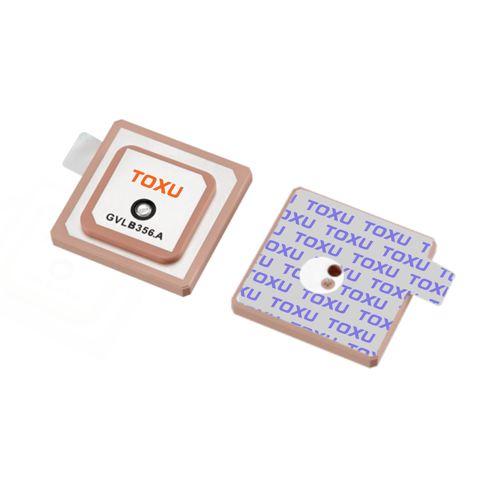
A passive GPS ceramic antenna is a type of microstrip patch antenna, a design known for its low profile and ease of integration. The "15x15mm" designation specifies its physical footprint, a compact square that has become a de facto standard in the industry, balancing performance with miniaturization. The term "passive" is a crucial differentiator; it means the antenna itself contains no active electronic components, such as a Low-Noise Amplifier (LNA). It relies entirely on the receiver's RF front-end to amplify and process the captured signal. This contrasts with "active" antennas, which integrate an LNA to boost the signal before it travels down a cable to the receiver. The passive nature makes it simpler, cheaper, and requires no external power, but it also means its performance is more susceptible to losses in the transmission line connecting it to the receiver.
The most defining material in its construction is the ceramic substrate. This is not ordinary ceramic but a specialized formulation with a very high dielectric constant (εr), typically ranging from 20 to 40 or even higher. This high εr is the key to its small size. The physical dimensions of an antenna are directly proportional to the wavelength of the target frequency. The GPS L1 frequency operates at 1575.42 MHz, corresponding to a free-space wavelength of approximately 19 centimeters. A traditional antenna might need to be a half or quarter of this size. However, the wavelength within a dielectric material is reduced by a factor of the square root of the dielectric constant (λ_d = λ_0 / √εr). A high εr of, say, 36 reduces the wavelength within the ceramic by a factor of 6, allowing the 15x15mm patch to be an efficient radiator at the GPS frequency despite being physically much smaller than the free-space wavelength.
The primary role of this antenna is to receive the Right-Hand Circularly Polarized (RHCP) signals transmitted by GPS satellites. These signals are incredibly weak by the time they traverse the atmosphere and reach the Earth's surface, with power levels often below -130 dBm. The antenna's job is to resonate at the target frequency, efficiently capture this faint energy, and transfer it via a matched transmission line (typically a 50-ohm microstrip trace on a printed circuit board) to the input of a GPS module or receiver chip.
The proliferation of the 15x15mm form factor is a story of market-driven standardization. As GPS evolved from a specialized military and surveying tool into a mass-market consumer technology for smartphones, wearables, asset trackers, and drones, the demand for a small, reliable, and low-cost antenna skyrocketed. The 15x15mm size proved to be a sweet spot: large enough to offer acceptable performance for most consumer-grade applications (typically providing 2-5 meter accuracy) and small enough to be tucked into the increasingly crowded interior of modern gadgets. Its flat, surface-mount technology (SMT) compatible design allows it to be automatically picked and placed by assembly robots, further driving down manufacturing costs.
In summary, the 15x15mm passive GPS ceramic antenna is a masterpiece of compromise and optimization. It sacrifices the raw performance and gain of larger, active, or survey-grade antennas to achieve the miniaturization, cost-effectiveness, and ease of integration required by the billion-unit consumer electronics market. It is the unsung hero of the location revolution, a tiny ceramic tile that silently listens to the whispers from space, enabling everything from navigating a new city to finding a lost pet.
The design and construction of a 15x15mm passive GPS ceramic antenna is a precise science, a delicate interplay of materials engineering, electromagnetic physics, and manufacturing pragmatism. While it appears as a simple, monolithic component, its internal architecture is carefully optimized to achieve the desired performance within its stringent dimensional constraints.
1. The Ceramic Substrate: The Foundation
The core of the antenna is the ceramic block itself. This is not a generic material but a proprietary compound, often based on titanium-based ceramics or other complex oxides, engineered to have specific electromagnetic properties.
High Dielectric Constant (εr): As established, this is the primary driver for miniaturization. A higher εr allows for a smaller antenna, but it comes with trade-offs. A very high εr (e.g., >40) can lead to excessively narrow bandwidth and lower radiation efficiency due to increased field concentration within the material itself. Therefore, manufacturers select a ceramic with an εr that strikes a balance—typically between 20 and 40—to ensure the antenna is both small and functional enough for the GPS L1 band.
Low Loss Tangent (tan δ): This parameter measures the rate at which energy is absorbed and lost as heat within the dielectric material. A low loss tangent (e.g., < 0.002) is critical for ensuring high efficiency. The antenna's job is to capture and radiate energy, not dissipate it. High-quality ceramics are formulated to minimize this loss.
Temperature Stability: The dielectric constant of all materials changes slightly with temperature. For a GPS antenna, this thermal drift can cause the resonant frequency to shift. High-grade ceramic blends are engineered to have a stable εr across a wide operating temperature range (e.g., -40°C to +85°C), ensuring consistent performance in various environments.
2. The Radiating Patch and Feed Point
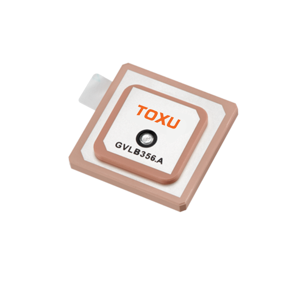
On the top surface of the ceramic block, a conductive radiating patch is deposited. This is typically a silver-based ink applied through a screen-printing process and then fired at high temperature to fuse it to the ceramic, creating a durable and low-resistance conductive layer.
Patch Geometry: The patch is most commonly square, as this geometry supports the resonant transverse magnetic (TM) mode required for operation. Its precise dimensions (slightly less than half the wavelength in the dielectric) are calculated to tune the antenna to resonate at precisely 1575.42 MHz.
Achieving Circular Polarization: GPS signals are RHCP. A simple square patch fed at one point produces linear polarization. To achieve circular polarization, the patch must be excited in two orthogonal modes with a 90-degree phase difference. This is most commonly done by introducing a physical perturbation to the patch's symmetry. A common design is the truncated corner patch, where two opposite corners of the square are cut off. The size of these truncations is meticulously calculated to split the resonant frequency into two slightly offset modes, which, when combined, create the desired circular polarization. The quality of this polarization is measured by the Axial Ratio; a lower, flatter axial ratio across the hemisphere is better.
3. The Ground Plane and Bottom Electrode
The bottom surface of the ceramic block is fully metallized, creating a continuous ground plane. This ground plane is fundamental to the antenna's operation:
Image Theory: The ground plane creates an electrical "image" of the radiating patch, effectively doubling the height of the antenna and significantly influencing its radiation characteristics.
Directionality: It makes the antenna directional, concentrating its radiation pattern in a hemisphere above the ground plane (towards the sky, where the satellites are) and providing inherent rejection of signals arriving from below.
Shielding: It helps to shield the antenna from noise and interference generated by the circuitry on the host PCB below it.
4. The Feed Mechanism
The antenna must be connected to the receiver. The standard method is a single feed point, often a soldering pad on the side or bottom of the component. The energy is coupled from the receiver's output trace on the PCB to this feed point. The impedance at the feed point must be matched to the system impedance (50 ohms) to ensure maximum power transfer. The location of the feed point on the patch is critical for achieving this match and for exciting the correct modes for circular polarization.
5. Integration with the Host PCB
A passive ceramic antenna does not operate in isolation; its performance is inextricably linked to the printed circuit board it is mounted on. The host PCB itself becomes part of the antenna system.
Keep-Out Area: A fundamental rule is that the ground plane on the host PCB must be removed from the area directly beneath and immediately surrounding the antenna. Copper pours or components in this "keep-out" area will detune the antenna, severely degrading its performance by capacitively loading it and altering its resonant frequency.
The PCB as a Ground Plane: While the area directly under the antenna is clear, the rest of the PCB's ground plane is essential. It acts as a counterpoise, extending the effective ground reference for the antenna. The size and shape of this PCB ground can influence the antenna's bandwidth and radiation pattern.
Matching Network: Even with a perfectly designed antenna, the impedance at the feed point may not be exactly 50 ohms across the entire GPS band. Therefore, a simple passive matching network, typically a Pi-network of capacitors and inductors, is placed on the PCB between the receiver chip and the antenna feed point. This network fine-tunes the impedance to ensure a conjugate match, maximizing power transfer.
The construction process involves precision sintering of the ceramic, accurate screen printing of the electrodes, and rigorous testing. Each batch is sampled to ensure it meets the target specifications for center frequency, bandwidth, return loss (S11), and axial ratio. The result is a robust, surface-mountable component that is both a marvel of material science and a testament to the demands of high-volume consumer electronics manufacturing.
The operation of the 15x15mm passive GPS ceramic antenna is a practical application of fundamental antenna theory, adapted and optimized for extreme miniaturization. Its working principle can be understood by examining how it resonates, how it achieves the correct polarization, how it couples to the circuit, and how its performance is affected by its integration environment.
Fundamental Resonance: The Half-Wave Patch
At its heart, the antenna operates as a resonant cavity. The top metallized patch and the bottom ground plane form the two conducting walls, and the ceramic material between them is the dielectric filling. The patch's length L is designed to be approximately half of the wavelength within the dielectric material (λ_d / 2) at the target frequency of 1575.42 MHz. When electromagnetic energy at this frequency is applied to the feed point, it excites a standing wave between the patch edges. The primary mode of operation is the TM₁₀ mode, where the electric field is oriented perpendicular to the patch surface and its magnitude varies sinusoidally along the length of the patch, reaching a maximum at the center and zero at the edges. The fringing fields at these radiating edges curl into the surrounding space and are responsible for the antenna's radiation.
Achieving Circular Polarization: The Truncated Corner Method
A key requirement for GPS reception is sensitivity to Right-Hand Circular Polarization (RHCP). A perfectly square patch fed at a single point produces linear polarization, where the electric field oscillates in a single plane. This is inefficient for receiving a circularly polarized signal, leading to a constant 3 dB polarization loss.
To create circular polarization, the antenna must radiate two orthogonal electric field components of equal amplitude but with a 90-degree phase difference. In the truncated corner method, the physical asymmetry introduced by cutting off two opposite corners perturbs the surface current paths on the patch. This perturbation splits the antenna's single resonant frequency into two closely spaced resonant frequencies, each associated with a different current mode. These two modes are orthogonal in space and, due to the nature of the perturbation, are naturally 90 degrees out of phase. When combined, these two fields generate a wave that rotates in a circular motion, creating either RHCP or LHCP (Left-Hand Circular Polarization), depending on which corners are truncated. The design is meticulously tuned to ensure this rotation is right-handed to match the GPS signals.
The Radiation Pattern and the Role of the Ground Plane
The presence of the ground plane fundamentally shapes the antenna's radiation pattern. According to image theory, the ground plane creates a virtual mirror image of the antenna below it. This results in a radiation pattern that is directional, with most of the energy being radiated in a hemisphere above the board. The pattern is not perfectly uniform; it typically has maximum gain at broadside (perpendicular to the patch surface) and gradually decreases towards the horizon. This is actually beneficial for GPS, as satellites are never directly below and are most commonly at elevations between 15 and 70 degrees above the horizon. The ground plane also provides a degree of inherent multipath rejection, as signals reflected from the ground and arriving from low elevation angles are attenuated.
Impedance Matching and Bandwidth
For maximum power transfer, the impedance of the antenna at its feed point must match the impedance of the transmission line feeding it (standardized at 50 ohms in most RF systems). The impedance of the patch antenna is influenced by the location of the feed point. Feeding it along the centerline provides a good match but only for a linear patch. For the circularly polarized truncated design, the feed point is located on the diagonal, offset from the center, to excite both orthogonal modes equally.
The "passive" nature of the antenna means it has a relatively narrow inherent bandwidth, often in the range of 10-30 MHz at the -10 dB return loss point. This is sufficient to cover the ~2 MHz bandwidth of the GPS C/A code signal but leaves little margin for error. This is why the impedance matching network on the host PCB is so critical. It compensates for small manufacturing tolerances and ensures the antenna operates at peak efficiency across the desired band.
The Complete Signal Path
Capture: RHCP electromagnetic waves from GPS satellites induce a tiny, oscillating current on the radiating patch.
Resonance: The patch resonates at 1575.42 MHz, amplifying the desired signal while rejecting others.
Transfer: The energy is coupled from the patch through the feed point.
Matching: The Pi-network matching circuit on the PCB ensures maximum power is transferred from the antenna to the transmission line.
Transmission: The signal, still extremely weak, travels via a 50-ohm microstrip trace to the input of the GPS receiver module.
Amplification: The receiver's integrated LNA (now inside the module, not the antenna) performs the critical first stage of amplification, boosting the signal for further processing.
The antenna's performance is highly dependent on its installation. Its resonance, bandwidth, and radiation pattern can be significantly detuned by nearby components, metal objects, or even the user's hand in a mobile device. Therefore, its working principle is not just about the component itself, but about the entire ecosystem in which it is placed. Careful PCB layout and adherence to the manufacturer's keep-out guidelines are essential for it to function as intended.
The widespread adoption of the 15x15mm passive GPS ceramic antenna is a direct result of its compelling advantages, which perfectly align with the needs of high-volume consumer electronics. However, these advantages are coupled with a set of distinct challenges that engineers must carefully manage during product design.
Advantages
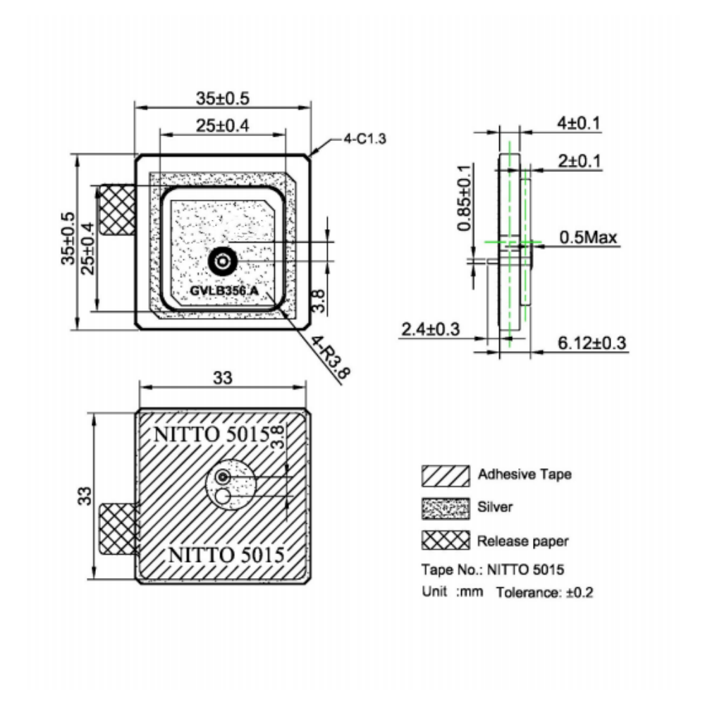
Extreme Miniaturization and Low Profile: This is its foremost advantage. The 15x15mm footprint and a height of often only 4mm allow it to be integrated into the slimmest of devices, including smartphones, watches, fitness trackers, and compact IoT sensors. Its surface-mount design contributes to a very low z-height, not protruding into the device's interior.
Low Cost and Suitability for Mass Production: The manufacturing process—based on ceramic sintering and screen printing—is highly scalable and automated. This allows these antennas to be produced in millions of units at a very low per-unit cost, often just a few dollars or even less. This economics is fundamental to its use in consumer goods.
Robustness and Reliability: The monolithic ceramic structure is mechanically rigid, resistant to vibration, and can withstand the high temperatures of reflow soldering. It is not susceptible to physical deformation like a flexible PCB antenna might be. Once soldered to the board, it becomes a very durable and reliable component.
Ease of Integration (SMT Compatibility): As a surface-mount device (SMD), it is perfectly suited for modern automated PCB assembly lines. Pick-and-place machines can handle it easily, and it goes through the same reflow oven as all other components, simplifying the manufacturing process and reducing assembly costs.
Good Performance for Consumer Applications: For its size, it provides entirely adequate performance for the vast majority of consumer use cases. When integrated correctly on a well-designed PCB, it can deliver the necessary gain pattern to achieve a position fix with 3-5 meter accuracy, which is sufficient for navigation, asset tracking, and location-based services.
No External Power Required: Being passive, it requires no bias voltage or current. This simplifies the design, reduces overall system power consumption (a critical factor for battery-powered devices), and eliminates a potential source of noise or failure.
Challenges and Limitations
Very Narrow Bandwidth: The high dielectric constant necessary for miniaturization comes at the cost of bandwidth. Its operational bandwidth is typically just wide enough to cover the GPS L1 band. This makes it a single-band antenna, incapable of leveraging modern multi-band (L2, L5) GNSS signals that offer better accuracy and faster convergence. It also means its performance is highly sensitive to manufacturing tolerances and environmental factors like temperature.
Performance Highly Dependent on Integration: This is arguably the biggest challenge for design engineers. The antenna's performance is not guaranteed by the component itself but is co-designed with the host PCB.
Keep-Out Area: The requirement for a large keep-out area (often a 20x20mm or larger region with no ground or components) can be difficult to achieve on a densely packed PCB, competing for valuable real estate.
Ground Plane Size: The size and shape of the PCB's ground plane significantly affect the antenna's bandwidth and radiation pattern. A too-small ground plane can cripple performance.
Environmental Effects: Proximity to plastic housings, batteries, displays, and even the user's hand can detune the antenna, shifting its resonant frequency and degrading performance. This requires extensive testing and tuning in the final product enclosure.
Lower Efficiency and Gain Compared to Larger Antennas: Due to its small size and high dielectric losses, its radiation efficiency is often lower than that of a larger patch or external active antenna. This translates to lower gain, making it more susceptible to signal dropouts in challenging environments like urban canyons or under dense foliage.
Limited to Single-Band (L1) Operation: The design is intrinsically tuned for the GPS L1 frequency. It cannot receive GLONASS G1, Galileo E1, or BeiDou B1 signals without compromising performance, and it is entirely blind to the modern L5/E5/B2a signals that are key to high-accuracy positioning. This limits the receiver's capability and future-proofness.
Sensitivity to Manufacturing Tolerances: Small variations in the ceramic's dielectric constant during production or slight misalignments in the screen-printing process can shift the center frequency. While matching networks can compensate for this, it adds variability that must be accounted for.
Lack of Amplification: As a passive antenna, it provides no gain. The weak signal it captures is then subject to loss in the transmission line to the receiver. Any cable or trace loss directly subtracts from the system's overall signal-to-noise ratio (SNR). This mandates that the receiver's LNA must have an exceptionally low noise figure to compensate.
In conclusion, the 15x15mm ceramic antenna is a tool of compromise. Its advantages of size, cost, and integrability make it the default choice for space- and cost-constrained consumer devices where "good enough" GPS performance is acceptable. Its challenges necessitate careful and experienced RF design to realize its potential and avoid disastrous performance failures.
Series 5: Applications and Future Trends of the 15x15mm Passive GPS Ceramic Antenna
The 15x15mm passive GPS ceramic antenna is a workhorse component that has enabled location awareness in a breathtaking array of modern devices. Its specific set of attributes—small size, low cost, and SMT compatibility—have made it the go-to solution for entire categories of electronics. However, as technology advances, its role is evolving amidst new trends and competing technologies.
Personal Navigation Devices and Smartphones: This was the original and remains a massive application. While smartphone antenna design has evolved to include integrated metal frame antennas for GNSS, the ceramic patch is still widely used in mid-range and budget devices, as well as in dedicated personal navigation devices, providing reliable location data for mapping and navigation apps.
Wearable Technology: Fitness trackers, smartwatches, and other wearables are ideal applications. Their extremely tight internal space demands the smallest possible components. A 15x15mm antenna provides just enough performance for tracking runs, hikes, and cycles without draining the small battery with active amplifier power.
Asset Tracking and IoT Sensors: The explosion of the Internet of Things (IoT) is a major driver. Small, low-power trackers for logistics, supply chain management, and theft prevention rely on these antennas to periodically report their location. Their low cost is critical for deploying sensors at scale.
Drones and Unmanned Aerial Vehicles (UAVs): Consumer and professional drones use these antennas for basic navigation and position holding. Their small size and weight are paramount in aviation, where every gram counts. They are often used in conjunction with other sensors like IMUs for stable flight.
Automotive Telematics and Aftermarket Devices: While high-end cars may use active roof-mounted antennas for navigation, passive ceramic antennas are found in lower-cost telematics units, usage-based insurance (UBI) dongles that plug into the OBD-II port, and aftermarket GPS units.
Consumer Electronics and Cameras: Digital cameras use them for geotagging photos. Handheld gaming devices might use them for location-based games. Even some laptops and tablets incorporate them for location services.
Future Trends
The future of this form factor is not about extinction but about evolution and finding its niche in a more complex technological landscape.
Niche Consolidation: The trend towards more integrated antenna solutions, like using sections of the smartphone's metal frame or printed LDS (Laser Direct Structuring) antennas on plastic housings, will continue in high-end devices. The 15x15mm ceramic antenna will increasingly become a solution for specific market segments: ultra-compact wearables, cost-sensitive IoT modules, and devices where its "fire-and-forget" reliability is valued over integration complexity.
Performance Enhancement via Hybrid Designs: To overcome the bandwidth limitation, we will see more "hybrid" ceramic antennas. These might incorporate multiple feed points or more complex internal structures to cover both L1 and L5 bands, or even to integrate other services like Bluetooth or Wi-Fi into the same ceramic footprint, saving space.
Improved Materials and Simulation: Advances in ceramic materials science may yield substrates with a more stable temperature coefficient or a better balance between dielectric constant and loss tangent. Furthermore, sophisticated 3D electromagnetic simulation tools (e.g., ANSYS HFSS, CST Studio) are making it easier for engineers to model the antenna's interaction with its entire environment before building a prototype, reducing design cycles and improving first-pass success.
The Rise of Multi-Band GNSS and the L5 Challenge: The biggest threat and opportunity is the adoption of multi-band GNSS. The L5 band offers significant advantages but operates at 1176.45 MHz, a frequency too far from L1 for a simple 15x15mm ceramic patch to cover effectively. Future devices requiring high accuracy will likely move towards larger antennas or different technologies. However, this will also drive innovation to create dual-band ceramic solutions, albeit with likely trade-offs in size or performance at each band.
Integration with Filtering: To improve resilience in the increasingly noisy RF environment, future iterations might integrate built-in passive filtering to reject out-of-band interference from cellular and other services, improving the SNR before the signal even reaches the receiver.
Sustainability and Material Sourcing: As with all electronics, there will be increasing pressure to ensure the materials used in these ceramics (e.g., titanium) are sourced responsibly and that the components are designed for recyclability, influencing future material choices.
The 15x15mm passive GPS ceramic antenna is not going away. Instead, its future lies in solidifying its role as the optimal solution for a well-defined set of applications where its core advantages of miniaturization, cost, and robustness outweigh the limitations of bandwidth and integration sensitivity. It will continue to be a fundamental enabler of the location-aware world, even as more advanced solutions emerge for the cutting edge.
Conclusion
The 15x15mm passive GPS ceramic antenna is a quintessential example of engineering pragmatism. It embodies the art of the possible within a set of rigid constraints, a testament to the innovation driven by the consumer electronics revolution. It is a component born not from a quest for ultimate performance, but from the relentless market pressures for smaller, cheaper, and more integrable solutions. In fulfilling this mandate, it has become one of the most ubiquitous antenna types in the world, silently powering the location capabilities of billions of devices.
Its design is a elegant solution to a complex physics problem: how to make an antenna electrically small without rendering it useless. The use of a high-dielectric-constant ceramic substrate is the key enabling technology, allowing it to resonate at the GPS L1 frequency within a minuscule volume. The truncated corner technique is a clever and cost-effective method to achieve the necessary circular polarization, while its surface-mount design dovetails perfectly with modern automated manufacturing.
The analysis of its advantages and challenges reveals its true nature as a component of compromise. Its unparalleled miniaturization and low cost are counterbalanced by its narrow bandwidth, integration sensitivity, and limited performance compared to larger alternatives. It is a component that demands expertise; its successful deployment is not guaranteed by the datasheet but is earned through careful PCB layout, adherence to keep-out rules, and thorough testing in the final product form factor.
Its applications are a map of the modern digital world, from the smartphone in your pocket to the tracker on a shipping container. It has democratized access to satellite navigation, bringing it from a specialized tool to a standard feature. As we look to the future, its role will evolve. It will cede ground in high-performance applications to multi-band and active antennas while simultaneously cementing its place as the optimal solution for the vast universe of compact, cost-driven, and battery-conscious IoT devices.
In the grand narrative of wireless technology, the 15x15mm passive GPS ceramic antenna may not be the hero that achieves centimeter-level accuracy. Instead, it is the unsung enabler, the reliable foot soldier that delivers "good enough" location data to the masses. It proves that in technology, sometimes the most impactful innovations are not those that push the absolute boundaries of performance, but those that master the trade-offs necessary to make a technology accessible, affordable, and universally available. It is a masterpiece of focused engineering, a tiny ceramic tile that has helped navigate the world.

 86 0755 2819 9597
Lucy Yang | lucy.y@toxutech.com
Nicole Li | nicole@toxutech.com
Dotty Zhao | sales04@toxutech.com
Global Business Director / Sales Team / Global Operations


 En
En Cn
Cn Korean
 Home >


