

-
Products -PCBA Manufacturing RF Connectors RF Cable Assemblys Embedded Antennas External Antennas GNSS Positioning Solutions
RF Connectors

RF Cable Assemblys
Embedded Antennas
External Antennas
GNSS Positioning Solutions





 Language


Language

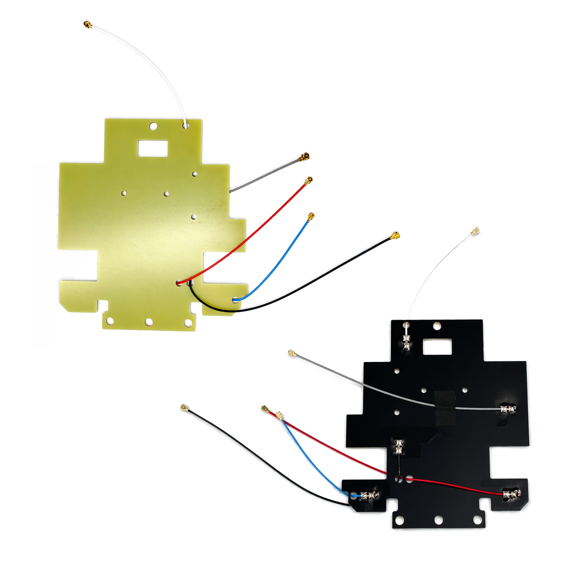
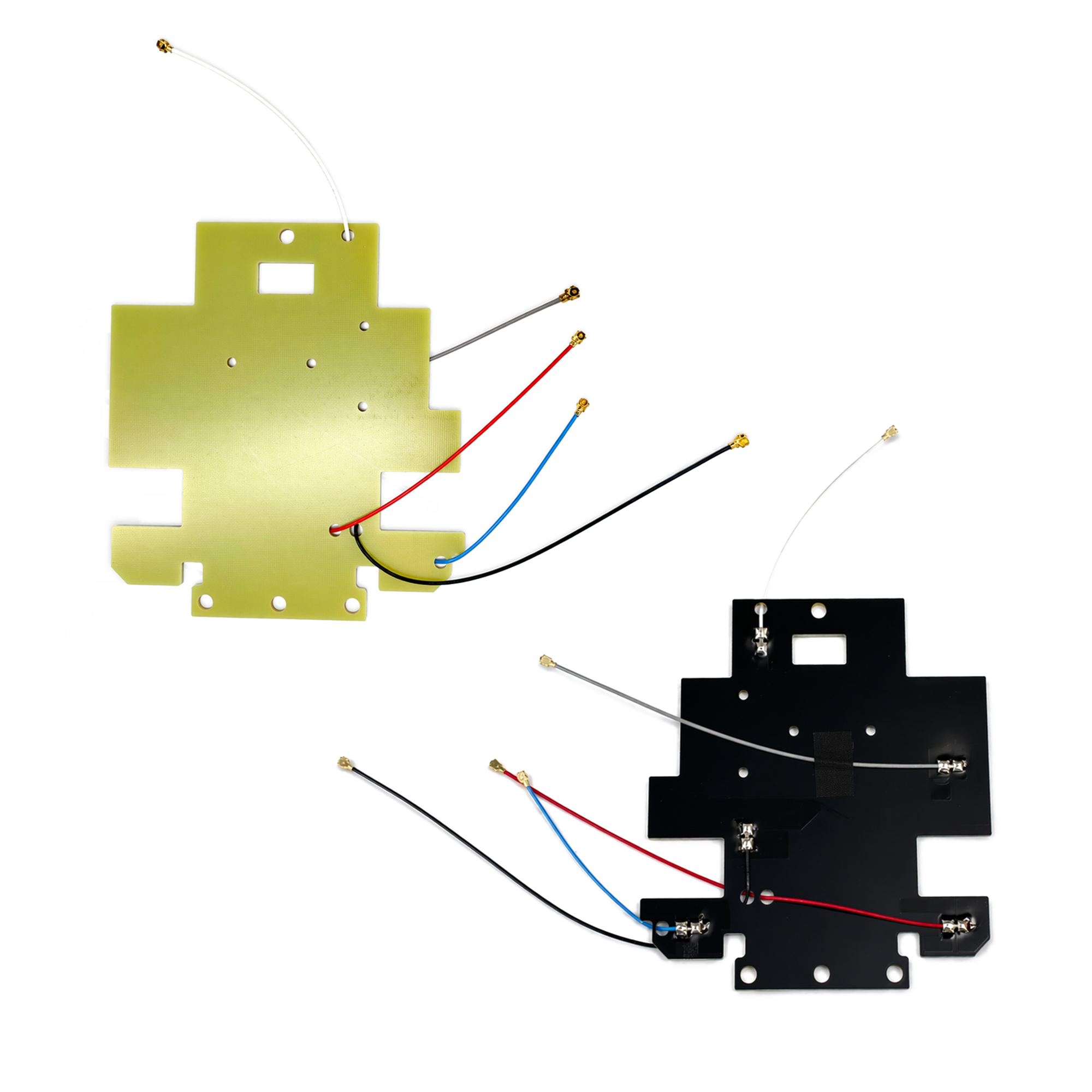
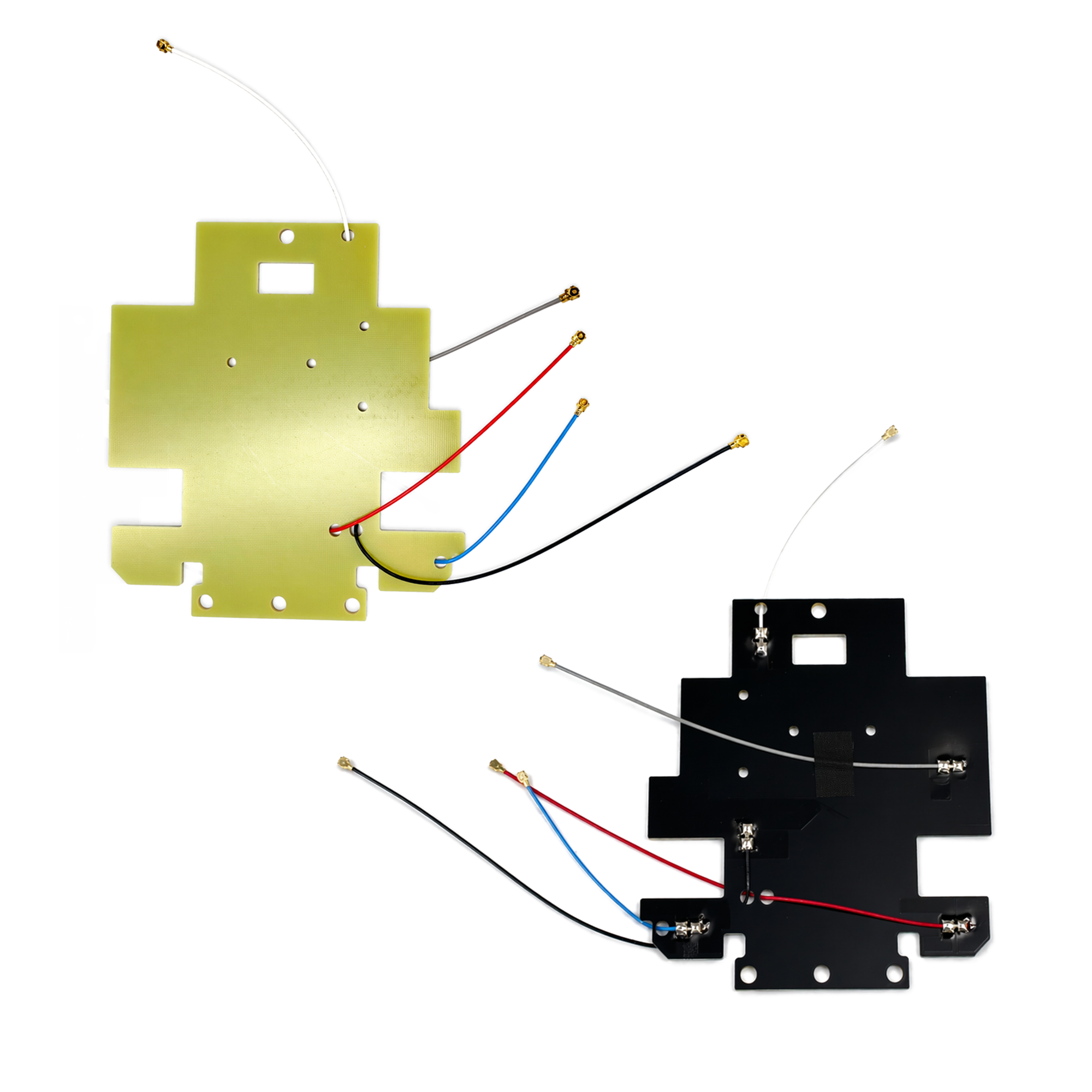
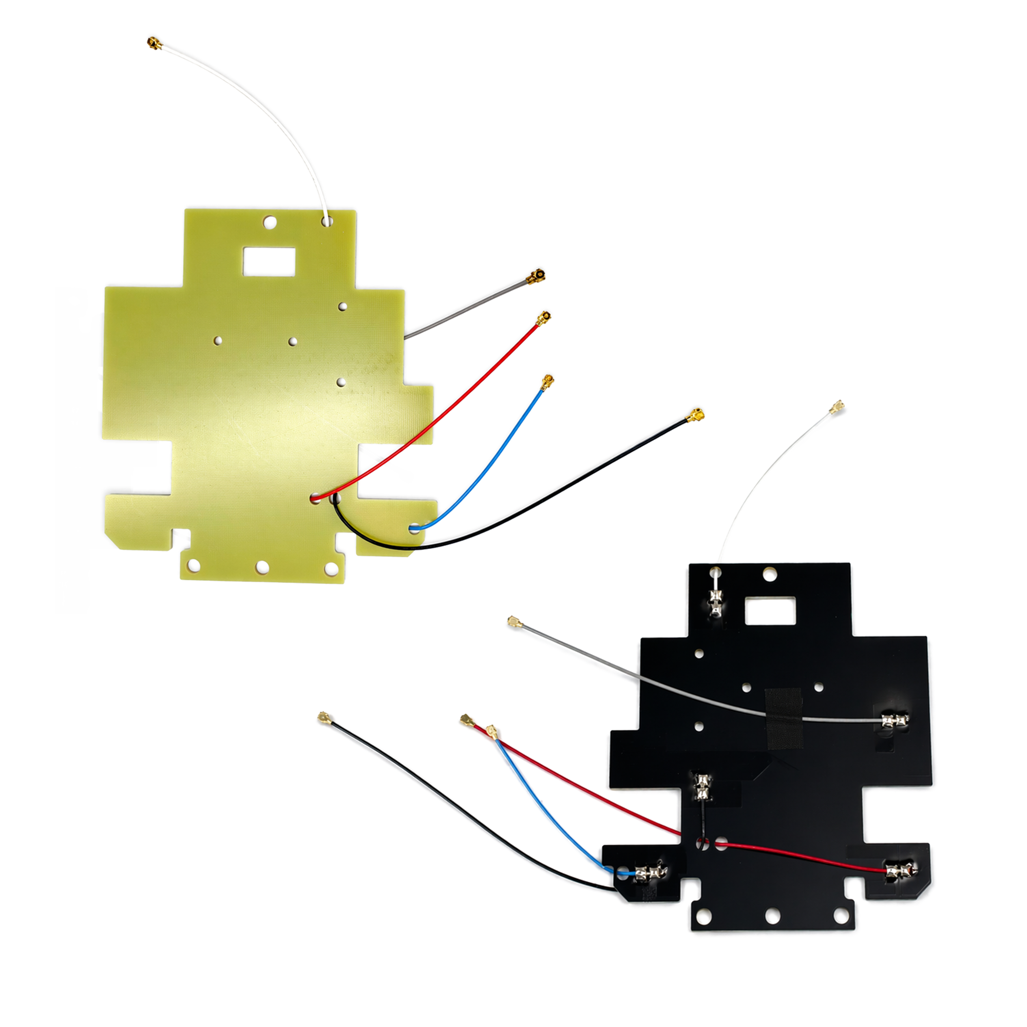
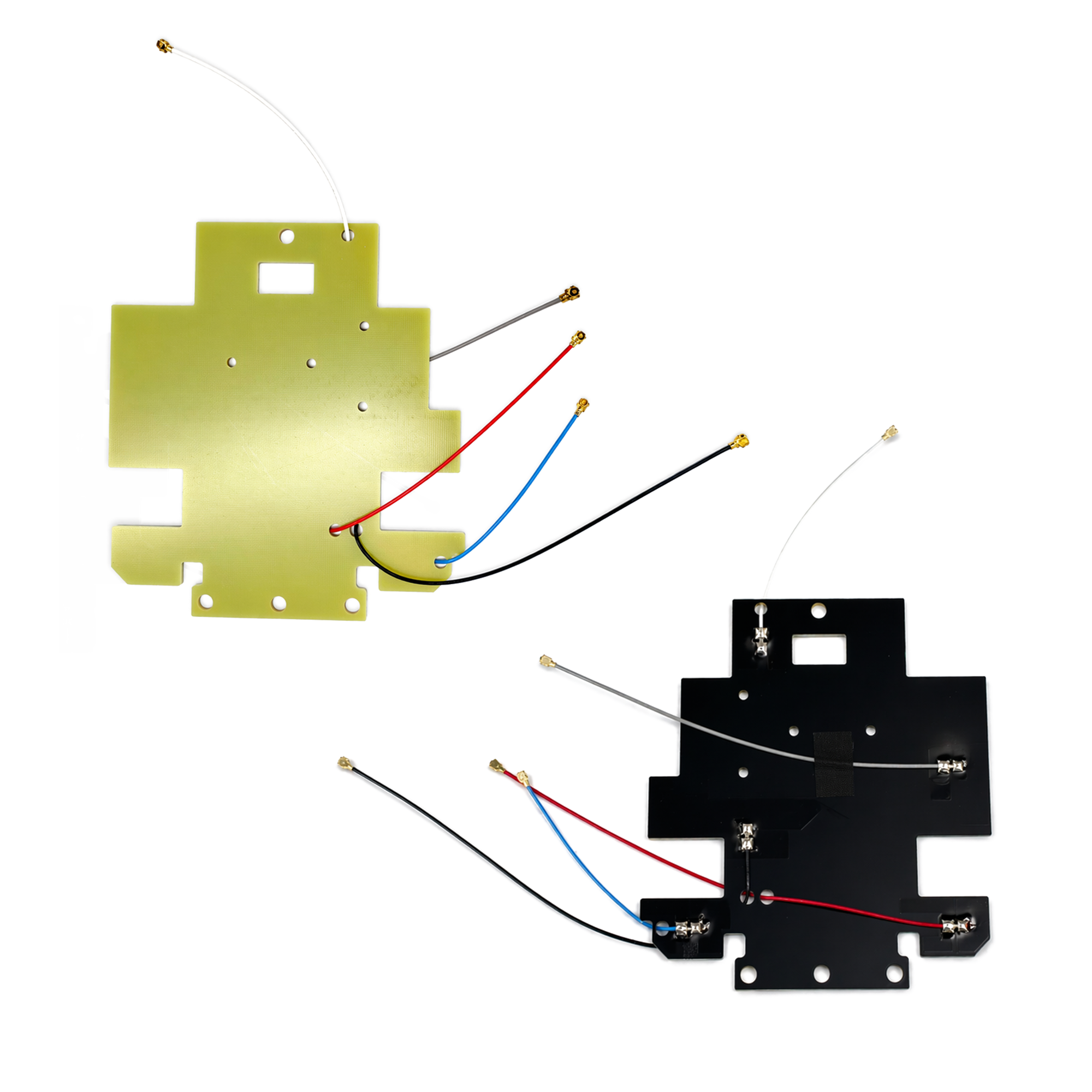

Model: KC.IA.00528
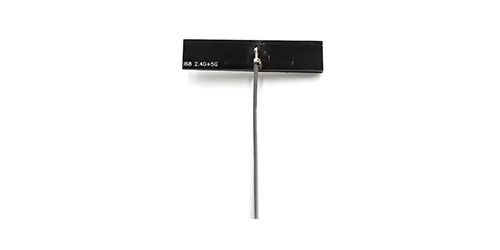
The TOXU KC.IA.00528 is an embedded dual-band Wi-Fi PCB antenna assembly with five color-coded coaxial leads for integration inside wireless devices.
Frequency Coverage: 2400–2500 MHz and 5150–5850 MHz.
Five RF Ports: Two leads for 2.4 GHz and three for 5 GHz.
PCB Size: 106 × 118 × 1.8 mm single-sided FR4 board.
RF Connection: 50 Ω RF1.13 coaxial leads with first-generation I-PEX-type plugs.
The TOXU KC.IA.00528 is a five-port embedded Wi-Fi antenna assembly for internal integration in wireless equipment. It combines two 2.4 GHz RF feeds and three 5 GHz RF feeds on one FR4 board. Each feed has a color-coded RF1.13 coaxial lead with a micro-coaxial plug.
Band-Specific RF Feeds
The gray and black leads are assigned to 2400–2500 MHz. The blue, white, and red leads are assigned to 5150–5850 MHz.
Color-Coded Coaxial Leads
Each lead has a defined length and color to help installers match it to the corresponding RF port. All five leads use 1.13 mm coaxial cable.
Contoured FR4 Board
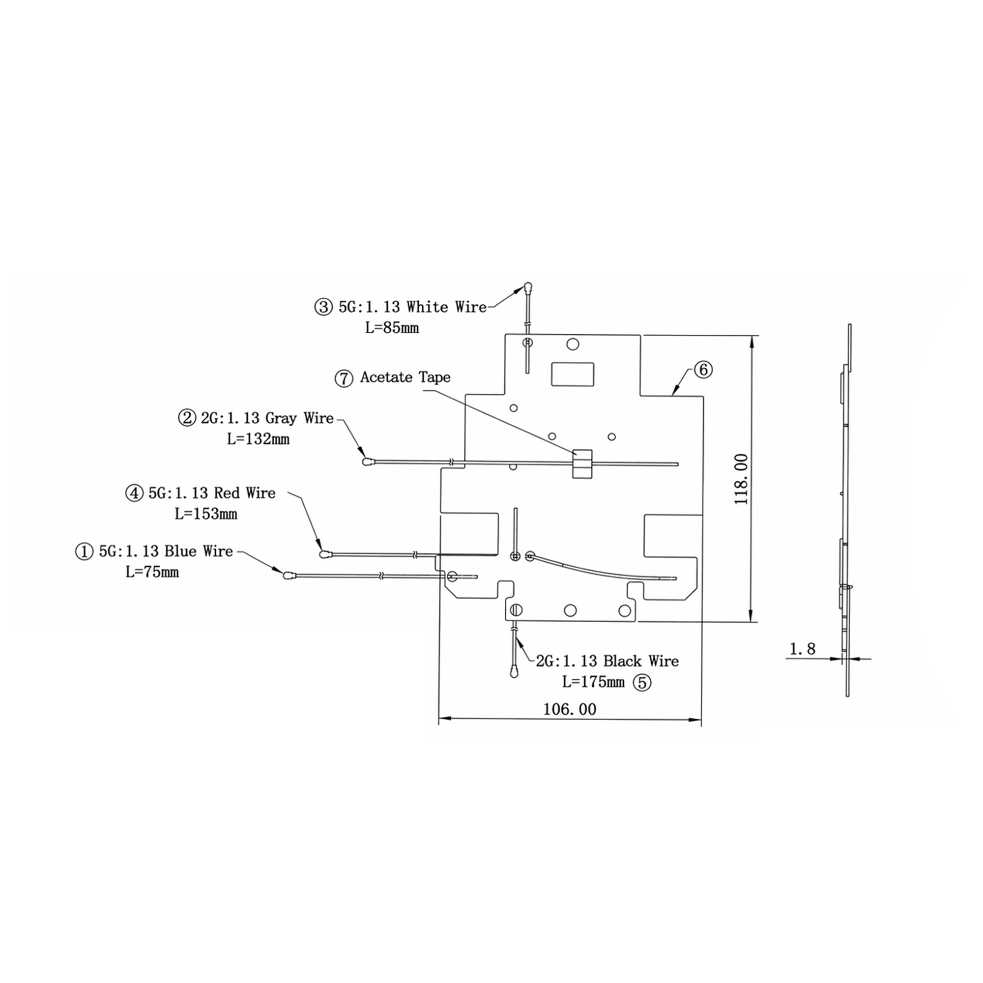
The 106 × 118 mm board has mounting holes and cutouts. The dimensional drawing shows the board outline and the location of each lead.
| Attribute | Value |
|---|---|
| Product Model | KC.IA.00528 |
| Antenna Type | Embedded dual-band Wi-Fi PCB antenna assembly |
| Frequency Range | 2400–2500 MHz / 5150–5850 MHz |
| RF Port Configuration | 2 × 2.4 GHz feeds and 3 × 5 GHz feeds |
| Nominal Impedance | 50 Ω |
| VSWR | < 3.0 |
| PCB Material | Single-sided FR4 |
| PCB Dimensions (W × H × T) | 106 × 118 × 1.8 mm |
| Cable Type | RF1.13 coaxial cable, 1.13 mm outer diameter |
| Connector | First-generation I-PEX-type micro-coaxial plug on each lead |
| 2.4 GHz Lead Lengths | Gray: 132 mm / Black: 175 mm |
| 5 GHz Lead Lengths | Blue: 75 mm / White: 85 mm / Red: 153 mm |
| Operating Temperature | −20 to +60 °C |
| Storage Temperature | −20 to +60 °C |
The drawing shows the PCB outline, mounting holes, cutouts, and the five lead positions. The 106 × 118 × 1.8 mm dimensions refer to the PCB. Lead lengths are specified separately by color.
Embedded antenna integration in dual-band Wi-Fi access points
Internal RF connections in compatible wireless routers and gateways
OEM Wi-Fi equipment with separate 2.4 GHz and 5 GHz RF ports
Match each lead to the correct radio port by frequency band and cable color. Verify the mating connector, board clearance, mounting hole positions, and cable reach before installation. Check RF performance in the fully assembled enclosure, where nearby metal and cable routing can affect the antenna response.
TOXU supplies the antenna as a pre-wired assembly. The dimensional drawing and color-to-band mapping give hardware teams the information they need to check fit and connections before evaluating samples.
Which leads connect to each Wi-Fi band?
Connect the gray and black leads to the 2.4 GHz RF ports. Connect the blue, white, and red leads to the 5 GHz RF ports.
How large is the antenna board?
The PCB measures 106 mm wide, 118 mm high, and 1.8 mm thick. Refer to the drawing for the board outline, mounting holes, and lead routing.
What connector is fitted to each lead?
Each lead terminates in a first-generation I-PEX-type micro-coaxial plug. Check that the receptacle on your radio module matches this interface before assembly.
Lucy Yang | lucy.y@toxutech.com
Dotty Zhao | sales04@toxutech.com
Global Business Director / Sales Team / Global Operations


 En
 Cn
 Korean
 Home >


