

-
Products -PCBA Manufacturing RF Connectors RF Cable Assemblys Embedded Antennas External Antennas GNSS Positioning Solutions
RF Connectors

RF Cable Assemblys
Embedded Antennas
External Antennas
GNSS Positioning Solutions
 Language


Language

Model: KC.IG.00154
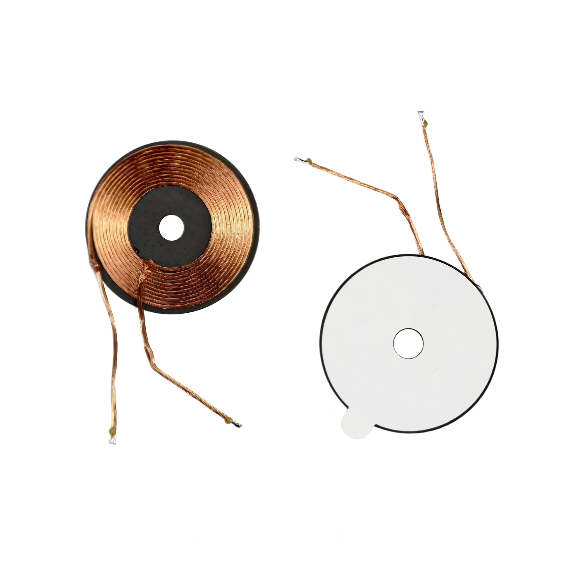
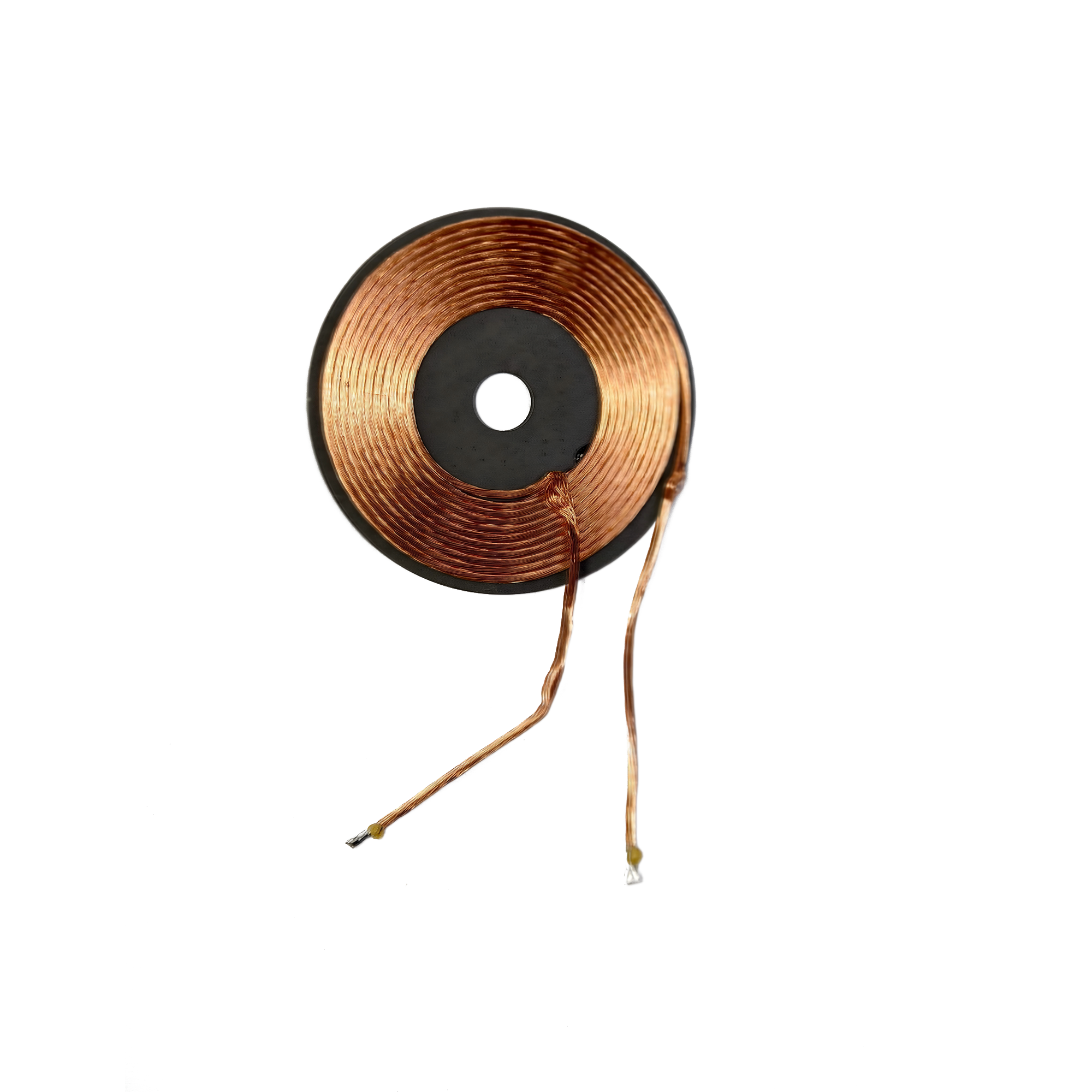
The TOXU KC.IG.00154 is a compact 6.3uH round wireless charging coil designed for internal installation in compatible handheld equipment and customized inductive charging systems. It combines a 35mm circular coil, ferrite backing, self-adhesive mounting and 35mm connection leads in a low-profile structure.
6.3uH Nominal Inductance:Provides a specified inductance of 6.3uH with a tolerance of +/-10%.
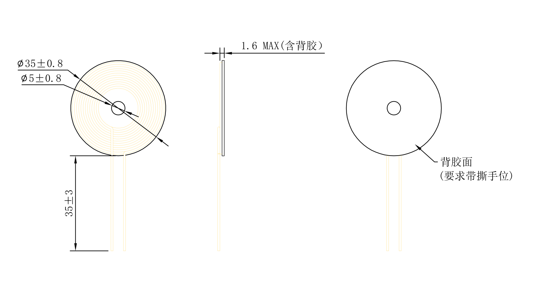
Compact Round Structure:Measures 35 +/-0.8mm in outer diameter and 5 +/-0.8mm in inner diameter.
Ferrite Backing:Uses an integrated ferrite layer to support magnetic flux management in the intended charging system.
Low-Profile Design:The maximum overall thickness is 1.6mm including the adhesive layer.
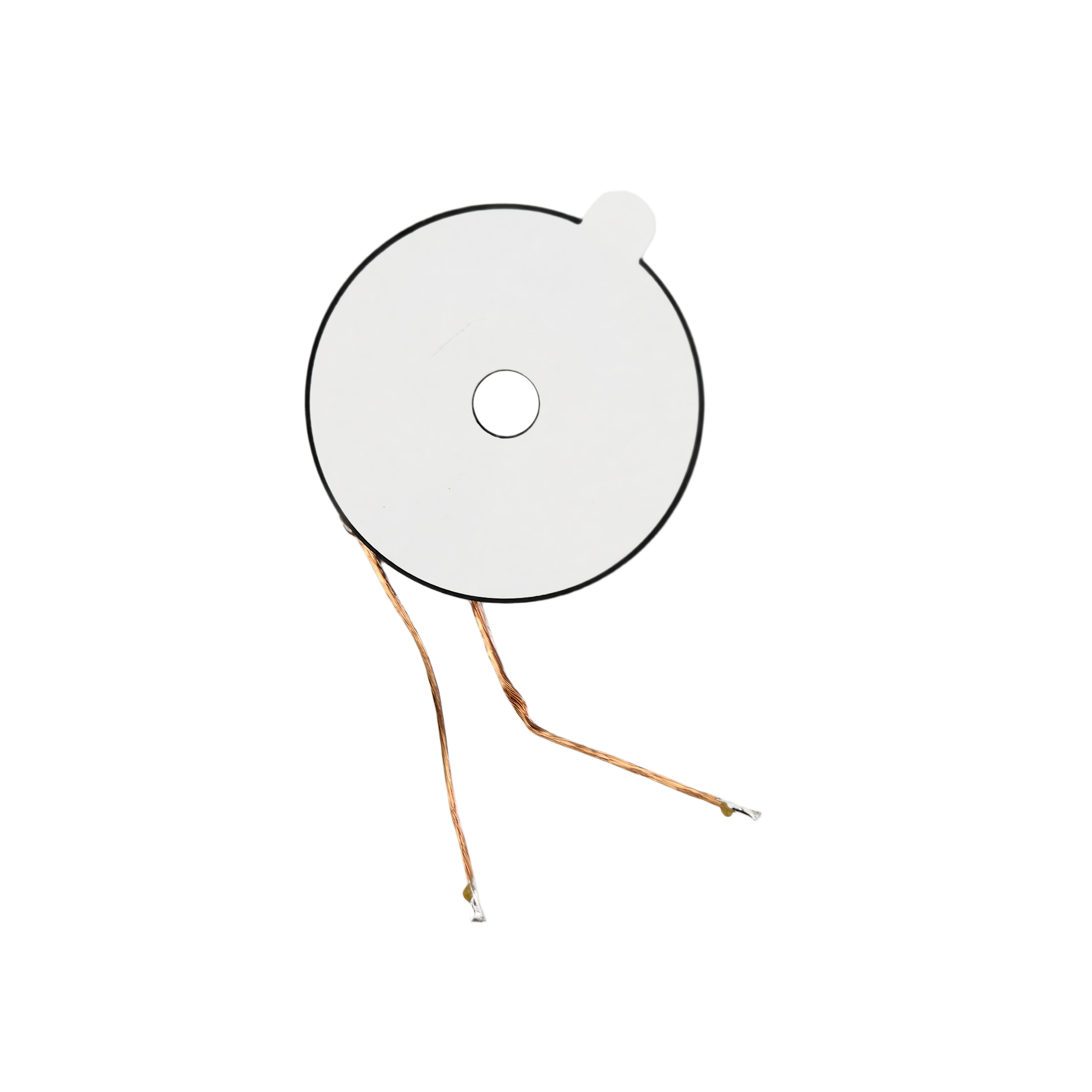
Self-Adhesive Installation:The rear adhesive surface includes a release tab for convenient internal equipment mounting.
Customizable Configuration:Inductance, coil dimensions, lead length, ferrite structure and adhesive configuration can be evaluated for volume-order projects.
The TOXU KC.IG.00154 is a compact round wireless charging coil designed for internal installation in compatible handheld devices, charging equipment and customized inductive power systems.
The coil has a nominal inductance of 6.3uH with a tolerance of +/-10%. Its circular structure measures 35 +/-0.8mm in outer diameter and 5 +/-0.8mm in inner diameter.
A ferrite backing layer is integrated with the coil to support magnetic flux management within the intended wireless charging system. The backing includes self-adhesive material for internal equipment installation.
The complete coil structure has a maximum thickness of 1.6mm including the adhesive layer. Its compact circular design supports integration into equipment with limited internal installation space.
Two 35 +/-3mm connection leads extend from the coil body for connection to a compatible wireless charging circuit.
The engineering drawing identifies KC.IG.00154 as the charging coil installed at the upper housing side of the intended equipment. This installation description does not independently confirm whether the coil operates as a transmitter or receiver.
Final charging performance depends on the charging IC, operating frequency, matching circuit, paired coil, coil alignment, transmission distance, enclosure material and surrounding metal components. Complete-system testing is required before volume production.
6.3uH Nominal Inductance
Provides a specified nominal inductance of 6.3uH with a tolerance of +/-10% for compatible wireless charging circuit designs.
Compact Round Structure
The coil measures 35 +/-0.8mm in outer diameter and 5 +/-0.8mm in inner diameter.
Ferrite Backing
The integrated ferrite backing supports magnetic flux management when used in a compatible inductive charging system.
Self-Adhesive Installation
The rear adhesive surface includes a release tab to support positioning and internal installation during equipment assembly.
Low-Profile Design
The complete structure has a maximum thickness of 1.6mm including the adhesive layer.
Pre-Attached Connection Leads
Two 35 +/-3mm leads are provided for connection to the intended wireless charging circuit.
Internal Equipment Integration
Designed for installation at the upper housing side of compatible handheld and customized wireless charging equipment.
Custom Project Support
Inductance, coil dimensions, lead length, ferrite structure, adhesive configuration and packaging can be evaluated according to project requirements and order quantity.
| TOXU Model | KC.IG.00154 |
| Product Type | Round Wireless Charging Coil |
| Nominal Inductance | 6.3uH |
| Inductance Tolerance | +/-10% |
| Outer Diameter | 35 +/-0.8mm |
| Inner Diameter | 5 +/-0.8mm |
| Maximum Thickness | 1.6mm Including Adhesive |
| Lead Length | 35 +/-3mm |
| Backing Material | Ferrite |
| Mounting Method | Self-Adhesive Mounting |
| Adhesive Structure | Adhesive Backing with Release Tab |
| Connection Method | Two Wire Leads |
| Installation Position | Upper Housing Side |
| Installation Type | Embedded / Internal Installation |
| Environmental Requirement | Complies with TOXU Restricted Substance Control Standard |
| Drawing Revision | A/0 |
The KC.IG.00154 uses a round coil structure with an outer diameter of 35 +/-0.8mm, an inner diameter of 5 +/-0.8mm and a maximum overall thickness of 1.6mm including the adhesive layer.
Two connection leads extend 35 +/-3mm from the coil body. The rear surface includes ferrite backing and self-adhesive material with a release tab.
Wireless Charging Handles
Handheld Electronic Devices
Personal Care Equipment
Portable Electronic Equipment
Rechargeable Consumer Devices
Smart Control Handles
Compact Inductive Power Systems
Embedded Wireless Charging Hardware
Customized Charging Equipment
The KC.IG.00154 is designed for integration with a compatible wireless charging circuit and a properly matched paired coil.
Wireless Charging Coil -> Matching Circuit -> Wireless Charging IC -> Power or Battery Circuit
Before selection, confirm that the nominal inductance of 6.3uH and the mechanical dimensions are compatible with the intended wireless charging IC, matching circuit and paired coil.
The engineering drawing specifies installation at the upper housing side of the intended equipment. The final coil position, orientation and adhesive surface should follow the approved equipment assembly design.
Coil alignment, separation distance, enclosure thickness and nearby metal components can materially affect charging efficiency, temperature rise and overall system stability.
The adhesive surface should be installed on a clean, dry and flat area. The ferrite backing and coil body must not be folded, crushed or subjected to excessive mechanical pressure.
Avoid sharply bending or repeatedly pulling the connection leads during assembly. Mechanical stress may damage the coil winding or lead connection.
The coil must be tested with the actual charging IC, matching circuit, paired coil, enclosure, battery and intended operating conditions before volume production.
TOXU supplies wireless charging coils, NFC antenna coils, embedded antennas, GNSS antennas, cellular antennas, Wi-Fi antennas, RF cable assemblies, coaxial connectors, modules and customized electronic hardware for equipment manufacturers and system integrators.
Our team can assist with coil dimension confirmation, inductance selection, backing structure, lead configuration, installation evaluation, sample preparation and complete-device testing.
For volume-order projects, TOXU can evaluate customized inductance values, coil dimensions, lead lengths, ferrite structures, adhesive configurations, labels and packaging.
With IATF16949 and ISO9001-certified manufacturing capabilities, TOXU supports component assembly, incoming material inspection, dimensional control, electrical testing, quality management and stable volume-order delivery.
Q: What is the inductance of KC.IG.00154?
A: The specified nominal inductance is 6.3uH with a tolerance of +/-10%.
Q: What are the coil dimensions?
A: The coil has an outer diameter of 35 +/-0.8mm, an inner diameter of 5 +/-0.8mm and a maximum thickness of 1.6mm including the adhesive.
Q: What backing material is used?
A: The engineering drawing specifies ferrite backing with a self-adhesive structure.
Q: How long are the connection leads?
A: The specified lead length is 35 +/-3mm.
Q: Is this an NFC antenna?
A: No. The supplied engineering drawing identifies KC.IG.00154 as a wireless charging coil rather than an NFC communication antenna.
Q: Is it a transmitter coil or receiver coil?
A: The drawing specifies installation at the upper housing side but does not define the coil as a transmitter or receiver. Its function must be confirmed according to the complete charging system design.
Q: Does it support the Qi wireless charging standard?
A: The available engineering drawing does not specify a wireless charging protocol. Compatibility depends on the charging IC, operating frequency, matching circuit, paired coil and complete-system test results.
Q: What charging power does the coil support?
A: Charging power is not specified in the available drawing. Inductance alone cannot determine the supported charging power.
Q: Can the coil specifications be customized?
A: Inductance, coil dimensions, lead length, ferrite structure and adhesive configuration can be evaluated according to project requirements and order quantity.
Q: Is complete-system testing required?
A: Yes. The coil must be tested with the actual charging IC, matching circuit, paired coil, enclosure and intended operating conditions before volume production.
Lucy Yang | lucy.y@toxutech.com
Dotty Zhao | sales04@toxutech.com
Global Business Director / Sales Team / Global Operations


 En
En Cn
Cn Korean
 Home >

