

-
Products -PCBA Manufacturing RF Connectors RF Cable Assemblys Embedded Antennas External Antennas GNSS Positioning Solutions
RF Connectors

RF Cable Assemblys
Embedded Antennas
External Antennas
GNSS Positioning Solutions







 Language


Language


Time:2026-10-17 Views:0
In an era where centimeter-level positioning has become the backbone of autonomous systems, precision agriculture, and next-generation IoT platforms, the antenna is no longer a commodity component—it is a strategic design decision. An OEM custom GNSS combo antenna integrates satellite navigation reception with complementary communication functions in a single, purpose-built solution, allowing device manufacturers to reduce bill-of-materials complexity, shrink form factors, and achieve performance that off-the-shelf products simply cannot deliver.
This guide examines why OEM custom GNSS combo antennas have become essential for modern positioning systems, how to specify them correctly, what technical trade-offs matter most, and how to evaluate suppliers in a rapidly evolving market.
What Is an OEM Custom GNSS Combo Antenna?
An OEM GNSS combo antenna is a multi-function antenna assembly designed specifically for integration into a host device—whether that is an autonomous vehicle, a robotic lawn mower, a UAV, or an industrial IoT gateway. The "combo" designation distinguishes it from standalone GNSS antennas by the integration of additional antenna elements within the same physical envelope.
The most common combinations include:
GNSS + Cellular (4G/5G): Supports both high-precision positioning and cloud connectivity through a single antenna unit. Taoglas's MA344 Series, for example, combines multi-band GNSS (L1/L5) with 2×2 wideband 5G/LTE MIMO in an IP67-rated enclosure measuring just 58.9 mm diameter × 65 mm height.
GNSS + Radio (LoRa/UHF): Critical for RTK systems that rely on local radio links for correction data. Harxon's HX-SE403A integrates full-band GNSS with a 915 MHz radio antenna in a single Φ122×23.8 mm housing, simplifying RTK system design and reducing production costs.
GNSS + Wi-Fi/Bluetooth: Common in asset trackers and wearable devices where multiple wireless technologies must coexist in a compact PCB area.
Multi-function "Super Combo": Advanced platforms may integrate GNSS with 5G MIMO, Wi-Fi MIMO, and V2X elements simultaneously. Taoglas's MA1047 SuperCombo, for instance, serves transportation, fleet management, autonomous driving, and emergency services applications in one vehicle-mount package.
The "custom" aspect is equally significant. Unlike catalog products, an OEM custom GNSS combo antenna is engineered to match a specific device's mechanical envelope, RF front-end impedance, connector type, cable routing, and environmental requirements. This level of tailoring is what separates a functional design from an optimized one.
Why Multi-Band GNSS Performance Matters
The transition from single-band to multi-band GNSS reception represents the single largest accuracy improvement available at the antenna level. Single-frequency antennas operating on L1 alone can achieve approximately 2–5 meters of accuracy in clear environments, but dual-band reception can bring that down to as good as one meter.
The physics behind this improvement is well understood. The ionosphere introduces a frequency-dependent delay to satellite signals. By receiving two or more frequencies—such as GPS L1 (1575.42 MHz) and L5 (1176.45 MHz)—a receiver can compute and eliminate the ionospheric delay through dual-frequency combination, achieving positioning accuracy at the centimeter or sub-meter level.
The three primary GNSS frequency bands serve distinct roles:
L1 (1575.42 MHz): The legacy band supported by all GNSS constellations. It offers the best compatibility and signal availability but is most susceptible to ionospheric delay and multipath interference.
L2 (1227.60 MHz): Primarily used for dual-frequency ionospheric correction. L2 signals are narrower in bandwidth and relatively weaker.
L5 (1176.45 MHz): The modern high-performance band, featuring a much wider bandwidth (10 MHz compared to L2C's 1 MHz) and higher transmitted power. L5 delivers superior performance in multipath and obstructed environments, making it the preferred choice for demanding applications.
Modern OEM custom GNSS combo antennas typically support full-band reception across multiple constellations. Harxon's HX-SE403A, for example, covers GPS L1/L2/L5, GLONASS L1/L2/L3, Galileo E1/E5a/E5b/E6, BDS B1I/B2I/B3I/B1C/B2a/B2b, QZSS L1/L2/L5/L6, IRNSS L5, and SBAS L1/L5—all from a single antenna element. This level of multi-constellation, multi-frequency coverage dramatically improves satellite availability and geometric dilution of precision (DOP), particularly in urban canyons and other challenging environments.
Key Technical Specifications for OEM Custom GNSS Combo Antennas
When specifying a custom combo antenna, engineers must evaluate a set of interdependent parameters. The following table summarizes the critical specifications and their typical values across different performance tiers:
| Parameter | Entry Level | Mid Range | High Precision |
|---|---|---|---|
| Frequency coverage | L1 only | L1 + L2 or L1 + L5 | Full-band L1/L2/L5 + all constellations |
| Peak gain (GNSS) | 0–2 dBiC | 2–4 dBiC | 4–7 dBiC |
| Axial ratio | ≤5 dB | ≤3 dB | ≤1–2 dB |
| Output VSWR | ≤2.0 | ≤2.0 | ≤1.5 |
| LNA gain | 20–28 dB | 28–35 dB | 35–40+ dB |
| Noise figure | ≤2.0 dB | ≤1.5 dB | ≤1.0 dB |
| Phase center stability | Not specified | ±5 mm | ±2 mm |
| Operating temperature | –20°C to +70°C | –40°C to +85°C | –40°C to +85°C |
Gain and Radiation Pattern
Gain in GNSS antennas is measured in dBiC (decibels relative to isotropic circular). For mobile applications, a minimum zenith gain of 3 dBiC is generally recommended, while base station and survey-grade designs may achieve 5–7 dBiC. However, higher gain is not universally better—the antenna's beamwidth must match the application. A half-power beamwidth of at least 120° ensures adequate low-elevation satellite tracking, which is critical for maintaining a robust position solution in obstructed environments.
Axial Ratio
Axial ratio measures the purity of circular polarization. A lower axial ratio—ideally below 3 dB—indicates better rejection of linearly polarized interference and reduced multipath error. Harxon's HX-CUX038A helix antenna achieves a typical axial ratio of just 1 dB, enabling excellent low-elevation signal reception even under tree canopies or near buildings.
Phase Center Stability
For RTK and other centimeter-level applications, phase center stability is arguably the most critical specification. The phase center is the apparent electrical point from which the antenna receives signals, and its variation with elevation and azimuth angle directly introduces positioning error. Advanced multipoint feeding technology is the key enabler here—Harxon's precision-tuned GNSS antennas achieve phase center errors of just ±2 mm, which is essential for maintaining baseline accuracy in RTK systems.
LNA and Noise Figure
Active GNSS combo antennas incorporate a low-noise amplifier (LNA) and often a SAW or BAW filter to compensate for cable loss and reject out-of-band interference. The noise figure (NF) of the LNA is the single most important determinant of weak-signal sensitivity. For high-precision applications, an NF of ≤1.0 dB is preferred, while ≤1.5 dB is acceptable for mid-range designs. LNA gain must be carefully matched to the cable length and receiver sensitivity—too little gain and the signal falls below the receiver's acquisition threshold; too much and intermodulation products degrade performance. Typical values range from 28–40 dB depending on configuration.
Isolation and Electromagnetic Compatibility
In combo antennas that integrate GNSS with cellular or radio elements, isolation between the elements is a critical design challenge. When multiple antennas are co-located in a single housing, near-field coupling can distort radiation patterns and cause gain suppression in certain directions, potentially pushing received signal strength below the receiver's capture threshold. Achieving adequate isolation requires careful element spacing, electromagnetic bandgap structures, and sometimes active filtering. Harxon's HX-SE403A addresses this through a compact integrated design that maintains excellent electromagnetic compatibility while keeping GNSS and radio feed points fully isolated.
The Customization Process: From Specification to Production
A well-structured OEM custom GNSS combo antenna development process typically follows five stages. Calian, a leader in custom GNSS antenna R&D, describes a three-step framework that has been refined across hundreds of projects: specification overview, feasibility study, and measurement/proposal.
Stage 1: Requirements Definition
The process begins with a thorough assessment of the application environment, performance targets, and physical constraints. Key questions include:
What accuracy level is required? Meter-level, sub-meter, or centimeter-level. This directly determines the frequency band coverage and phase center stability requirements.
What is the installation environment? Rooftop, embedded in a handheld device, mounted on a vibrating platform, or exposed to marine conditions. This drives the radome material, sealing strategy, and mounting interface.
What other radios must coexist? Cellular, Wi-Fi, LoRa, or V2X. Each additional element adds coupling and filtering complexity.
What are the mechanical constraints? Available PCB area, maximum height, connector type, and cable routing path.
Stage 2: Feasibility Study and Antenna Selection
With requirements defined, the antenna manufacturer evaluates candidate architectures—patch, helix, or printed FPC—and performs electromagnetic simulation using tools such as HFSS or CST. Critical simulation studies include impedance matching across the target frequency bands, axial ratio optimization, and full-system coupling analysis with the host PCB and enclosure.
For patch antennas, the ground plane is not optional—it is part of the antenna. A ground plane with a diameter or diagonal of at least half the maximum wavelength (λmax/2) is recommended to achieve stable radiation patterns and adequate bandwidth. For GNSS frequencies around 1.2–1.6 GHz, this translates to a PCB of at least 70×70 mm. If the host device cannot provide this, a helix or FPC antenna may be the better choice.
Stage 3: Prototyping and Tuning
The first physical prototypes are measured in an anechoic chamber to characterize radiation patterns, gain, axial ratio, and VSWR across the full operating band. Phase center calibration may be performed using a three-coordinate measurement system with a reference antenna to determine X, Y, and Z offsets.
OEM GNSS antennas are easily detuned by the local environment—the host PCB, nearby metal components, and the enclosure all shift the resonant frequency. Custom tuning services are therefore essential. Harxon notes that its OEM antennas are "easily detuned by the local environment" and offers tuning as part of its standard customization offering.
Stage 4: Integration Testing
Once the antenna is integrated into the host device, real-world testing validates performance in the actual mechanical configuration. This includes outdoor road tests recording signal-to-noise ratio (SNR), visible and usable satellite counts, DOP values, and positioning success rate. Multipath testing in urban canyons, near water surfaces, and around buildings provides additional confidence.
For combo antennas, integration testing must also verify isolation between GNSS and cellular elements under worst-case transmit conditions. When a 5G or LTE modem is transmitting at full power, the GNSS front-end must remain free from desensitization.
Stage 5: Production and Quality Assurance
Production-grade OEM custom GNSS combo antennas undergo rigorous quality control. Key production processes include vacuum epoxy potting to protect internal PCBs, LNAs, and coaxial feeds from moisture and vibration; automated VNA calibration to verify impedance matching on every unit; and thermal cycling to validate solder joint integrity under temperature extremes. Suppliers with ISO 9001 certification and in-house anechoic chambers provide the most reliable quality assurance.
Connector and Cable Customization
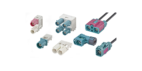
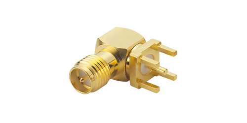
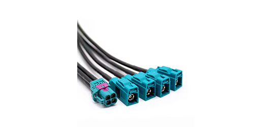
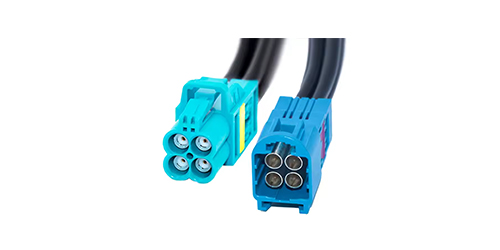
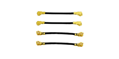
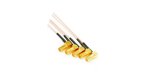
The physical interface between the antenna and the host device is often overlooked during specification but can make or break integration. Standard connector options include SMA, MMCX, MCX, IPEX (1–5 generation), FAKRA, and TNC, with the choice depending on frequency range, mating durability, and available space.
Cable type and length also matter. For GNSS signals in the 1.2–1.6 GHz range, a 1.13 mm diameter coaxial cable introduces approximately 0.5–1.0 dB of loss per 100 mm. While the active LNA compensates for this loss, excessive cable length can degrade the noise figure if the LNA gain is insufficient. For automotive and outdoor installations, low-loss cables such as RG174 or specialized RF cables are preferred, routed away from power supply lines and high-current switching circuits.
Harxon's HX-SE402A exemplifies this flexibility: the standard version ships with an MCX-C-JW connector and IPEX I Male for the radio element, but both cable length and connector type can be customized upon request to match the host device's interface.

Application Scenarios Driving Custom GNSS Combo Antenna Demand
Autonomous Vehicles and Robotics
Autonomous ground robots, delivery vehicles, and robotic lawn mowers demand continuous centimeter-level positioning with minimal integration complexity. Harxon's HX-ME407A Smart Antenna consolidates GNSS multi-frequency reception, RTK engine, 4G modem, LoRa transceiver, and MCU into a single ruggedized device, reducing wiring, lowering weight, and eliminating assembly risks associated with managing separate modules. For fleet-scale deployments, this integration translates to measurable reductions in maintenance workload and part lifecycle management costs.
Precision Agriculture
Agricultural machinery guidance systems require robust GNSS performance in environments with dust, vibration, and challenging satellite visibility. Multi-band combo antennas with integrated radio links enable real-time RTK correction without additional hardware, improving pass-to-pass accuracy and reducing overlap during planting and spraying operations.
UAV and Surveying
Lightweight UAV platforms have severe size, weight, and power constraints. Harxon's HX-CUX038A weighs just 15 grams and measures Φ44×73.9 mm, yet supports full-band GNSS including GPS L1/L2/L5, GLONASS L1/L2/L3, Galileo E1/E5a/E5b/E6, BDS B1/B2/B3, and L-Band, along with 4G connectivity. This level of integration enables survey-grade positioning on small airframes that previously required multiple antennas and receivers.
Fleet Management and Industrial IoT
Fleet telematics systems need reliable positioning and high-speed connectivity across diverse geographic regions. Taoglas's MA344 Series provides GNSS coverage for GPS, GLONASS, Galileo, BeiDou, QZSS, IRNSS, and SBAS alongside 2×2 MIMO cellular covering 600–6000 MHz for global 4G LTE and 5G connectivity. Its IP67-rated magnetic mount enables fast, non-destructive installation on leased vehicles and temporary deployments.
Market Trends and Industry Outlook
The global market for positioning antennas is expanding at a pace that reflects the growing ubiquity of location-aware systems. The global positioning antenna market was estimated at USD 3.64 billion in 2026 and is projected to reach USD 7.76 billion by 2033, representing a compound annual growth rate of 11.4%. Within this broader market, the embedded GNSS active antenna segment—which encompasses most OEM combo antennas—was valued at USD 227 million in 2025 and is forecast to reach USD 300 million by 2032, growing at a CAGR of 3.7%.
Several trends are shaping the OEM custom GNSS combo antenna landscape:
Higher levels of integration. The trajectory is clear: from single-function GNSS antennas to multi-function combo units that replace discrete components. This reduces PCB area, simplifies cable routing, and improves electromagnetic compatibility through factory-optimized element spacing and filtering.
Full-band becoming mainstream. As L5/E5a signals become more widely available and RTK/PPP services proliferate, full-band GNSS reception is transitioning from a premium feature to a baseline expectation. Antennas that support only L1 will increasingly struggle to meet accuracy requirements in professional applications.
Ceramic 3D printing and advanced materials. Manufacturers are exploring additive manufacturing for ceramic antenna elements, enabling faster prototyping and more complex geometries that were previously impractical with conventional machining.
Tighter integration with RTK engines. The next generation of combo antennas embeds the RTK positioning engine directly within the antenna housing, eliminating the separate receiver module and reducing the overall system footprint.
Stringent automotive-grade requirements. As GNSS becomes safety-critical for autonomous driving, antennas must meet AEC-Q200 and ISO 16750 standards for temperature cycling, vibration, and humidity resistance.
How to Choose the Right OEM Custom GNSS Combo Antenna Supplier
Selecting a supplier for a custom combo antenna is a long-term partnership decision. The following criteria should guide evaluation:
Technical depth and simulation capability. A supplier that relies solely on empirical tuning will struggle with complex integration challenges. Look for in-house HFSS/CST simulation capability, anechoic chamber testing facilities, and a track record of solving difficult co-existence problems.
Customization flexibility. The best OEM partners offer not just standard product catalogs but true custom engineering—from PCB layout and impedance matching to connector selection, cable assembly, and radome design. Harxon's full-chain manufacturing capability covers microwave material selection, passive component design, RF circuit tuning, and antenna integration in a seamless flow from requirement to finished product.
Production quality systems. ISO 9001 certification is the minimum. For automotive and industrial applications, IATF 16949 and AEC-Q200 compliance are strong indicators of a supplier capable of meeting demanding reliability standards.
Lead times and scalability. Time-to-market is often the decisive factor. Suppliers that offer fast prototyping (typically 2–4 weeks for first articles) and can scale to volume production without sacrificing consistency have a clear advantage. Signal Plus Technology, for example, advertises design customization within three days for certain antenna configurations.
Application engineering support. The best suppliers act as design partners, not just component vendors. They help system integrators navigate the trade-offs between gain, bandwidth, phase center stability, and cost—and they understand that the "best" antenna is the one that works reliably in the target environment, not the one with the highest datasheet numbers.
An OEM custom GNSS combo antenna is more than a component—it is an enabling technology for the next generation of autonomous, connected, and location-aware products. By integrating multi-band GNSS reception with cellular, radio, or Wi-Fi elements in a single optimized assembly, these antennas reduce system complexity, improve electromagnetic compatibility, and deliver positioning performance that meets the most demanding accuracy requirements.
The specification process demands careful attention to frequency coverage, gain, axial ratio, phase center stability, LNA noise figure, and isolation between co-located elements. The development cycle—from requirements definition through prototyping, integration testing, and volume production—requires a supplier with deep RF engineering expertise, advanced simulation and measurement capabilities, and a genuine commitment to customization.
As the market for positioning antennas accelerates toward USD 7.76 billion by 2033, the companies that invest early in well-specified, properly integrated OEM custom GNSS combo antennas will be best positioned to deliver products that meet the accuracy, reliability, and cost targets of tomorrow's applications. Whether the target is a robotic lawn mower navigating a suburban yard, a survey drone mapping remote terrain, or an autonomous delivery fleet operating in dense urban environments, the antenna is where positioning performance begins—and where system-level optimization delivers its greatest returns.
For engineers and system integrators evaluating OEM custom GNSS combo antennas, the advice is straightforward: define the application requirements first, prioritize phase center stability and isolation over raw gain figures, validate performance in the actual integration environment, and partner with a supplier that treats customization as a core competency rather than an afterthought. The investment in getting the antenna right pays dividends throughout the product lifecycle.
Lucy Yang | lucy.y@toxutech.com
Dotty Zhao | sales04@toxutech.com
Global Business Director / Sales Team / Global Operations


 En
 Cn
 Korean
 Home >
