

-
Products -PCBA Manufacturing RF Connectors RF Cable Assemblys Embedded Antennas External Antennas GNSS Positioning Solutions
RF Connectors

RF Cable Assemblys
Embedded Antennas
External Antennas
GNSS Positioning Solutions





 Language


Language


Time:2026-10-17 Views:0
Why Low Profile GNSS 4G Antennas Are Transforming Wireless Connectivity
As IoT deployments expand across fleet management, smart cities, asset tracking, and industrial automation, the demand for antennas that deliver reliable GNSS positioning alongside 4G LTE communication in an increasingly compact form factor has never been greater. The low profile GNSS 4G antenna has emerged as a critical component in this ecosystem, offering engineers and system integrators a solution that combines multi-band connectivity with discreet, space-efficient physical designs.
Traditional antenna installations often require multiple separate components—one for GNSS, one or more for cellular, and additional elements for Wi-Fi or other bands. This approach consumes valuable real estate, complicates cable management, and increases installation labor costs. Low profile combination antennas address these challenges by integrating GNSS, 4G LTE, and often Wi-Fi or Bluetooth functionality into a single low-profile housing.
This guide provides a comprehensive exploration of low profile GNSS 4G antennas, covering the technical principles behind their design, key performance specifications, real-world applications, selection criteria, and installation best practices. Whether you are designing a fleet tracking system, building smart city infrastructure, or deploying IoT gateways, understanding these antennas will help you make informed decisions that balance performance, durability, and cost.
What Is a Low Profile GNSS 4G Antenna?
Defining the Low Profile Form Factor
A low profile GNSS 4G antenna is a multi-band combination antenna designed to house GNSS (Global Navigation Satellite System) reception and 4G LTE cellular communication capabilities—and frequently additional bands such as Wi-Fi—within a slim, compact enclosure. The term "low profile" typically refers to antennas with a height of 20mm or less, though some manufacturers define the threshold at 30mm depending on the mounting context.
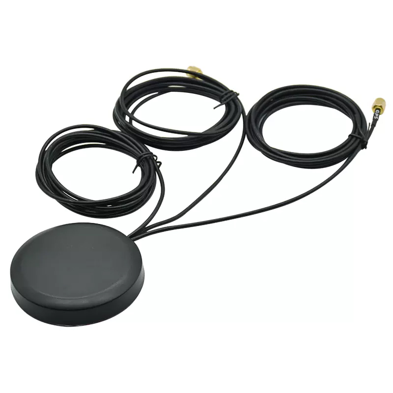
These antennas are commonly available in puck-style (circular dome), adhesive-mount, and screw-mount configurations. Their slim silhouettes make them ideal for applications where visual discretion, aerodynamic efficiency, or vandal resistance is essential. Unlike traditional whip or shark-fin antennas that protrude significantly from the mounting surface, low profile designs sit flush or near-flush, reducing the risk of damage from tree branches, low clearances, or deliberate tampering.
The Convergence of GNSS and 4G in a Single Antenna
The integration of GNSS and 4G LTE into a single antenna represents a significant engineering achievement. GNSS signals operate in the L-band around 1559–1606 MHz, while 4G LTE spans 698–960 MHz and 1710–2690 MHz, with 5G extending up to 6000 MHz. Housing both bands in close proximity requires careful attention to electromagnetic isolation, preventing the higher-power cellular transmission from interfering with the extremely weak GNSS signals.
Modern combination antennas achieve this through advanced filtering, dual-feed GNSS patch designs, and physical separation of radiating elements within the enclosure. These innovations ensure that both positioning and communication functions perform reliably without mutual degradation.
Low Profile vs Standard Antennas: A Technical Comparison
Form Factor and Installation Trade-offs
The most obvious difference between low profile and standard antennas is physical size. Standard whip antennas can extend 100mm or more from the mounting surface, while shark-fin designs typically reach 65mm in height. Low profile PIFA (Planar Inverted-F Antenna) designs, by contrast, measure approximately 25mm in height, and advanced puck designs can go as low as 15.5mm.
This reduction in height affects antenna gain and radiation patterns. Standard antennas, particularly those with longer radiating elements, often deliver higher peak gain. However, for mobile and IoT applications, the difference in practical performance is frequently offset by the system-level benefits: simpler installation, reduced wind loading, and the ability to mount on surfaces where taller antennas would be impractical or vulnerable.
Radiation Pattern and Gain Considerations
Radiation patterns differ meaningfully between antenna types. A typical low profile PIFA element offers omnidirectional coverage suitable for cellular communication, but its vertical radiation toward the sky—critical for GNSS reception—may be somewhat reduced compared to a dedicated patch antenna. Manufacturers address this by using dual-feed GNSS patch elements within combination antennas, which provide excellent axial ratio and gain despite the compact overall dimensions.
For GNSS specifically, low profile combination antennas often incorporate active low-noise amplifier (LNA) modules with gains ranging from 18 dB to 30 dB. This active amplification compensates for the inherently weaker signal capture of a smaller antenna element, ensuring reliable satellite acquisition even in challenging urban environments.
The Metal Surface Challenge
One significant technical consideration for low profile antennas is their behavior when mounted on conductive surfaces such as vehicle roofs or metal enclosures. A metal surface can reflect and cancel antenna currents, degrading radiation efficiency and causing impedance mismatch. However, recent innovations have produced antennas specifically engineered for metal mounting. Taoglas' Comet series, for example, leverages proprietary all-metal PIFA designs that deliver at least 20% performance improvement over similar alternatives when installed on flat metallic surfaces.
This development is particularly important for automotive and industrial applications, where metal mounting surfaces are the norm rather than the exception.
Key Technical Specifications to Evaluate
Frequency Band Coverage
When selecting a low profile GNSS 4G antenna, frequency coverage is the first specification to evaluate. For 4G LTE, a comprehensive antenna should cover:
Low bands: 698–960 MHz (including LTE Band 12, 13, 14, 17, 20, and 28)
Mid/high bands: 1710–2690 MHz (covering LTE Band 1, 2, 3, 4, 7, and 41)
For GNSS, the antenna should support the full L1 band from 1559 to 1606 MHz, encompassing GPS, GLONASS, Galileo, BeiDou, and QZSS constellations. Some advanced models also cover the L5 band (1164–1189 MHz) for enhanced positioning accuracy. Wideband designs that extend to 6000 MHz also provide future-proofing for 5G NR deployment, ensuring that the antenna remains viable as cellular networks evolve.
VSWR and Return Loss
Voltage Standing Wave Ratio (VSWR) indicates how efficiently power transfers from the transmission line to the antenna. For combination antennas, VSWR should ideally be ≤2.0:1 across all operating bands, with premium models achieving ≤1.5:1. A VSWR of 2.0:1 corresponds to approximately 90% power transfer efficiency, while 1.5:1 achieves around 96%. Lower VSWR translates directly to stronger signal reception and transmission, particularly important for GNSS where signal levels are already extremely low.
GNSS LNA Gain and Noise Figure
Since GNSS signals arriving at the antenna are exceptionally weak (typically around -130 dBm), an integrated LNA is essential. The LNA amplifies the satellite signal before it travels through the coaxial cable to the receiver. Two parameters are critical:
Gain: Ranges from 18 dB to 35 dB in low profile combination antennas. Higher gain helps overcome cable losses but must be balanced against the receiver's dynamic range.
Noise Figure (NF): The lower, the better. Premium LNAs achieve noise figures below 1.5 dB, with some reaching 0.8 dB. A low noise figure ensures that the amplified signal remains clean and usable.
The LNA is typically powered through the coaxial cable (bias tee), with voltage requirements of 1.5–5.5 V DC.
Isolation Between Antenna Elements
Isolation measures how much signal from one antenna element leaks into another. In a combination antenna, the 4G transmitter (which can output up to 2W or more) must not desensitize the GNSS receiver. Good isolation—typically 15 dB or better—is achieved through physical separation, orientation, and filtering. Manufacturers often incorporate pre-filter LNAs specifically designed to reject LTE Band 13/14 interference, which operates near the GNSS band.
Environmental and Mechanical Ratings
Low profile antennas for outdoor and vehicle applications must withstand demanding environmental conditions. Key ratings include:
IP Rating: IP67 (dust-tight, water immersion up to 1m) is the standard for outdoor use. IP69K offers enhanced protection against high-pressure, high-temperature water jets, suitable for commercial vehicle wash-downs.
Impact Resistance: IK10 indicates resistance to 20 joules of impact, equivalent to a 5 kg object dropped from 40 cm.
Operating Temperature: -40°C to +85°C is the standard range for automotive and industrial applications.
Material: UV-resistant ASA or PC/ABS enclosures with flame-retardant properties (UL94-V0) ensure long-term outdoor durability.
Dimensions and Mounting Options
Low profile GNSS 4G antennas are available in several form factors:
| Mounting Type | Typical Dimensions | Best For |
|---|---|---|
| Adhesive mount | 152 × 59 × 13 mm | Light vehicles, temporary installations |
| Screw mount (puck) | Ø 46–81 mm × 15–17 mm | Permanent installations, heavy-duty vehicles |
| Panel mount | Ø 180 mm × 80 mm | Industrial enclosures, base stations |
Screw and panel mount options provide the most secure installation for harsh environments, while adhesive mounting avoids drilling and is suitable for applications where the antenna may need to be repositioned or removed.
GNSS Performance Deep Dive
Multi-Constellation Support
Modern low profile GNSS antennas support multiple satellite constellations simultaneously, including GPS (USA), GLONASS (Russia), Galileo (EU), BeiDou (China), and QZSS (Japan). This multi-constellation capability dramatically improves positioning reliability in urban canyons, dense foliage, and other environments where a single constellation might have insufficient visible satellites. Dual-feed GNSS patch designs within combination antennas ensure excellent axial ratio across all supported constellations, maintaining accurate circular polarization reception.
Active Antenna Architecture
An active GNSS antenna incorporates a low-noise amplifier directly at the antenna element, before the signal travels through the coaxial cable. This architecture is essential because cable losses at GNSS frequencies can be significant—a 5-meter RG174 cable, for example, can attenuate the signal by 3–4 dB. By amplifying before the loss occurs, the LNA preserves the signal-to-noise ratio, which is the critical factor for reliable positioning.
The LNA typically includes a pre-filter to reject out-of-band interference. This is particularly important in combination antennas, where the 4G transmitter's harmonics and intermodulation products can fall within the GNSS band. Advanced filtering for LTE Band 13 (777–787 MHz) and Band 14 (788–798 MHz) is a common feature, as these bands are closest to GNSS frequencies and most likely to cause interference.
Signal Acquisition in Challenging Environments
In urban canyons, underground parking structures, and dense forests, GNSS signals are attenuated and subject to multipath reflections. Low profile antennas with high LNA gain (28–35 dB) and low noise figures (<1.5 dB) perform best in these conditions. The circular polarization of the GNSS patch element helps reject multipath signals that have undergone polarization changes during reflection, further improving positioning accuracy.
4G LTE and 5G Compatibility
Coverage of Global LTE Bands
A well-designed low profile GNSS 4G antenna should cover all major LTE bands used worldwide. The 698–960 MHz range encompasses the low-frequency bands favored by many carriers for wide-area coverage, while 1710–2690 MHz covers the mid and high bands used for capacity. Backward compatibility with 3G and 2G networks ensures functionality in regions where older networks remain in operation.
Many current-generation antennas also support LTE Cat-M and Narrowband IoT (NB-IoT) protocols, which are optimized for low-power, wide-area IoT applications such as smart metering and asset tracking.
MIMO Capabilities
Multiple-Input Multiple-Output (MIMO) technology is fundamental to achieving the data rates expected from modern LTE networks. Low profile combination antennas typically offer 2×2 MIMO as a minimum, with high-end models supporting 4×4 MIMO for maximum throughput. MIMO requires multiple cellular antenna elements within the same enclosure, which must maintain good isolation from each other (typically ≥10 dB) as well as from the GNSS element.
Preparing for 5G
The transition to 5G introduces new frequency bands, including the C-band (3.4–4.2 GHz) and various millimeter-wave bands. While millimeter-wave requires different antenna technologies, many low profile combination antennas now cover the sub-6 GHz 5G bands from 600 to 6000 MHz, ensuring compatibility with current and planned 5G deployments. This wideband capability provides investment protection, allowing the same antenna to serve 4G today and 5G tomorrow.
Applications and Use Cases
Fleet Management and Vehicle Telematics
Fleet management systems rely on continuous GNSS positioning and reliable 4G connectivity to track vehicles, monitor driver behavior, and enable real-time dispatch. Low profile GNSS 4G antennas are ideal for this application because they can be mounted on vehicle roofs or trunks without creating aerodynamic drag or visual clutter. The combination of GNSS and 4G in a single unit simplifies installation, reducing labor costs and potential points of failure.
A typical fleet telematics installation might use a screw-mount combination antenna with 2×2 MIMO 4G and active GNSS, connected to the telematics control unit via SMA or FAKRA connectors. The antenna's IP67 or IP69K rating ensures reliable operation through rain, snow, and vehicle wash-downs.
Smart City Infrastructure
Smart city deployments—including connected lighting, traffic management systems, environmental sensors, and waste management—require antennas that blend into urban infrastructure. Low profile puck antennas mounted on light poles, traffic signals, or utility cabinets provide the necessary GNSS and 4G connectivity without the visual impact of traditional whip antennas. Their vandal-resistant designs are particularly important in public spaces.
Asset Tracking and Logistics
For asset tracking applications, adhesive-mount low profile antennas offer a compelling combination of ease of installation and reliable performance. These antennas can be attached to shipping containers, trailers, or high-value equipment without drilling, making them suitable for both permanent and temporary deployments. The compact dimensions—some as small as 152 × 59 × 13 mm—allow them to be mounted in locations where larger antennas would not fit.
Industrial IoT and Remote Monitoring
Industrial environments present unique challenges for antenna performance: metal surfaces, electromagnetic interference from machinery, and extreme temperatures. Low profile GNSS 4G antennas designed for industrial use incorporate features such as metal-surface-optimized radiation patterns, wide operating temperature ranges, and robust connector systems (SMA, FAKRA, NMO) that maintain reliable connections under vibration.
Public Safety and Emergency Response
Public safety vehicles—police cars, ambulances, fire trucks—require dependable communication and positioning for dispatch, navigation, and situational awareness. Low profile combination antennas provide the multi-band connectivity needed for these mission-critical applications, with the added benefit of reduced risk of damage during high-speed operations or in confined spaces.
How to Select the Right Low Profile GNSS 4G Antenna
Step 1: Define Your Frequency Requirements
Begin by identifying the cellular bands used by your network operator in your deployment region. If you are deploying globally, ensure the antenna covers all relevant bands. For GNSS, confirm support for the constellations your receiver uses. If your application requires high-precision positioning, consider an antenna with L1/L5 dual-band GNSS capability.
Step 2: Assess Your Environmental Conditions
Determine the IP rating required for your installation. IP67 is sufficient for most outdoor applications, while IP69K is recommended for applications subject to high-pressure wash-downs. Consider the operating temperature range and whether UV resistance is important for your mounting location.
Step 3: Choose Your Mounting Method
Adhesive mounting is fastest and requires no drilling, making it suitable for light vehicles and temporary installations. Screw mounting provides the most secure installation for heavy-duty and permanent applications. Panel mounting is appropriate for industrial enclosures and base station equipment.
Step 4: Verify Electrical Compatibility
Check that the antenna's impedance (typically 50 Ω) matches your system, and confirm that the VSWR is acceptable across your operating bands. Ensure that the LNA voltage requirements are compatible with your receiver's bias tee. Verify that the connector type (SMA, FAKRA, NMO) matches your equipment.
Step 5: Evaluate Cable and Connector Options
Antenna cables introduce loss, particularly at GNSS frequencies. Choose low-loss cable types (such as TGC-200 or equivalent) for longer cable runs, and keep cable lengths as short as practical. Custom cable lengths and connector configurations are often available from manufacturers to match specific installation requirements.
Step 6: Consider Future-Proofing
If your deployment timeline extends beyond the current network generation, select an antenna that covers the 5G sub-6 GHz bands (up to 6000 MHz). This ensures that your antenna investment remains viable as networks evolve, avoiding the need for costly replacement during the system's operational life.
Installation Best Practices
Ground Plane Considerations
Most low profile GNSS 4G antennas are designed to operate with a ground plane, which is typically provided by the metal surface of the vehicle roof or enclosure. The ground plane size affects antenna performance—a larger ground plane generally improves gain and bandwidth. For installations on non-conductive surfaces, a metallic ground plane of at least 100 × 100 mm should be provided beneath the antenna.
Some antennas are specifically designed to be ground-plane independent, using dipole or balanced antenna structures. These are suitable for installations on fiberglass, plastic, or other non-conductive surfaces.
Cable Routing and Strain Relief
Route antenna cables away from noise sources such as motors, ignition systems, and power cables. Use grommets or cable glands where cables pass through metal panels to prevent chafing. Provide strain relief near the antenna and the receiver to prevent stress on connectors. For GNSS cables, minimize bends and avoid sharp angles, which can degrade signal quality.
Connector Mating and Weatherproofing
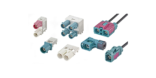
Ensure that all connectors are fully mated and properly torqued. For outdoor installations, apply silicone grease or self-amalgamating tape to connector interfaces to prevent moisture ingress. Even IP67-rated antennas can fail if water enters through improperly sealed connectors. FAKRA connectors, commonly used in automotive applications, provide a positive lock and are color-coded to prevent mismating.
Testing and Validation
After installation, verify antenna performance using a GNSS signal strength indicator and a cellular signal meter. Check that the GNSS receiver achieves a satisfactory fix within the expected time (typically 30 seconds for a cold start with active antenna). For cellular, verify that the received signal strength (RSSI) and signal quality (SINR) are within acceptable ranges. If performance is below expectations, check connector integrity, cable routing, and ground plane connections before considering antenna replacement.
Common Challenges and Solutions
GNSS Interference from 4G Transmissions
One of the most common challenges in combination antenna installations is GNSS interference from the 4G transmitter. This manifests as degraded positioning accuracy, longer time-to-first-fix, or complete loss of GNSS lock when the cellular modem is transmitting. Solutions include:
Selecting an antenna with a pre-filtered LNA designed to reject LTE Band 13/14 interference
Ensuring adequate isolation between GNSS and cellular elements (≥15 dB)
Using a GNSS receiver with good out-of-band rejection
Keeping the GNSS cable as short as possible to minimize the chance of interference pickup
Multipath in Urban Environments
In cities with tall buildings, GNSS signals reflect off structures, creating multipath that degrades positioning accuracy. Antennas with good circular polarization purity (low axial ratio) are more resistant to multipath, as reflected signals typically have altered polarization. Dual-feed GNSS patch designs with axial ratios below 3 dB provide the best multipath rejection.
Cable Loss at GNSS Frequencies
Coaxial cable loss increases with frequency. At 1575 MHz, RG174 cable exhibits approximately 0.7 dB/m loss, while low-loss cables such as TGC-200 reduce this to around 0.3 dB/m. For installations where cable runs exceed 3 meters, low-loss cable is strongly recommended. Alternatively, locating the GNSS receiver closer to the antenna can minimize cable losses.
Frequently Asked Questions
What is the difference between an active and passive GNSS antenna?
A passive GNSS antenna contains only the radiating element, while an active antenna includes a low-noise amplifier (LNA) that amplifies the signal before it travels through the cable. Active antennas are essential for most vehicle and IoT applications because they overcome cable losses and provide the signal strength needed for reliable positioning. All low profile GNSS 4G combination antennas discussed in this guide are active designs.
Can I use a low profile GNSS 4G antenna with a 5G modem?
Yes, provided the antenna covers the 5G frequency bands used by your network. Most modern low profile combination antennas support sub-6 GHz 5G (up to 6000 MHz), which encompasses the C-band and other key 5G frequencies. However, millimeter-wave 5G requires different antenna technology and is not supported by these antennas.
How do I know if my antenna is properly grounded?
Most low profile antennas are designed for mounting on metal surfaces that serve as the ground plane. If you are mounting on a non-conductive surface, you may need to provide a metallic ground plane. Check the antenna datasheet for specific grounding requirements. A simple test involves comparing GNSS signal strength and cellular performance with and without the ground plane in place.
What is the typical lifespan of a low profile GNSS 4G antenna?
With proper installation and a quality product, a low profile GNSS 4G antenna can provide 10 years or more of reliable service. The key factors affecting lifespan are UV exposure, temperature cycling, and moisture ingress. Antennas with UV-resistant ASA enclosures and IP67/IP69K ratings are designed for long-term outdoor deployment.
Can I mount a low profile antenna on a plastic or fiberglass surface?
Yes, but you should choose a ground-plane-independent antenna design. These antennas use dipole or balanced structures that do not rely on a metallic ground plane for proper operation. If you use a standard ground-plane-dependent antenna on a non-conductive surface, performance will be significantly degraded.
The low profile GNSS 4G antenna represents a mature and highly capable solution for applications that demand reliable positioning and communication in a compact, durable package. From fleet telematics to smart city infrastructure, these antennas deliver the multi-band performance that modern IoT deployments require, without the installation complexity and vulnerability of traditional antenna systems.
When selecting an antenna for your project, focus on the fundamentals: frequency coverage that matches your network and constellation requirements, isolation between GNSS and cellular elements, environmental ratings appropriate to your installation environment, and a mounting method that suits your mechanical constraints. Pay attention to the GNSS LNA specifications—gain and noise figure—as these directly determine positioning reliability in challenging environments.
As cellular networks evolve toward 5G and satellite constellations continue to expand, the importance of well-designed combination antennas will only grow. Investing in a quality low profile GNSS 4G antenna today provides a foundation for reliable connectivity that will serve your application for years to come. Whether you are building a fleet of connected vehicles, deploying smart city sensors, or designing industrial IoT gateways, the right antenna is the first and most critical link in your wireless chain.
Lucy Yang | lucy.y@toxutech.com
Dotty Zhao | sales04@toxutech.com
Global Business Director / Sales Team / Global Operations


 En
 Cn
 Korean
 Home >
