

-
Products -PCBA Manufacturing RF Connectors RF Cable Assemblys Embedded Antennas External Antennas GNSS Positioning Solutions
RF Connectors

RF Cable Assemblys
Embedded Antennas
External Antennas
GNSS Positioning Solutions







 Language


Language


Time:2026-10-17 Views:0
Why the Antenna Is the Most Overlooked Component in Fleet Telematics
Every fleet tracking system rests on a deceptively simple premise: a vehicle must know where it is, and that information must reach a dispatcher, a cloud platform, or a control center in real time. The modem, the SIM card, the tracking software, and the dashboard all get the attention. The antenna—the one component that actually captures the GNSS signal and transmits the LTE data—is too often an afterthought. That oversight costs fleets money, uptime, and operational visibility.
A fleet tracking LTE GNSS antenna is a combined radio-frequency device that integrates cellular connectivity (LTE, and increasingly 5G) with satellite-based positioning (GPS, GLONASS, Galileo, BeiDou) in a single housing. These combo antennas have become the default choice for telematics deployments because they reduce installation complexity, lower total hardware cost, and improve signal reliability compared with separate single-function antennas. But not all combo antennas are equal. Frequency coverage, gain, isolation, ingress protection, mounting style, and regulatory certification all determine whether a fleet gets the reliable tracking data it paid for—or a stream of gaps, inaccuracies, and maintenance tickets.
This guide examines the technical foundations of LTE GNSS antennas for fleet tracking, the selection criteria that matter most, installation best practices, regulatory considerations, and the business case for getting the antenna right the first time.
The Role of the Antenna in Fleet Tracking Architecture
How Fleet Tracking Systems Use LTE and GNSS Together
A modern fleet tracking system performs three core functions: positioning, data transmission, and timing. GNSS provides the first and third. The antenna receives signals from satellite constellations orbiting roughly 20,000 kilometers above the Earth, extracts the time-of-arrival data encoded in those signals, and passes them to a receiver that calculates latitude, longitude, altitude, speed, and heading. LTE provides the second function: a two-way data link that carries position reports, sensor telemetry, driver behavior data, and over-the-air commands between the vehicle and the fleet management platform.
The antenna sits at the boundary between the vehicle and both wireless domains. Its GNSS element must capture extremely weak satellite signals—by the time a GPS signal reaches the Earth’s surface, its power is on the order of -160 dBm, well below the thermal noise floor of most receivers. The LTE element must transmit and receive across multiple frequency bands, often simultaneously, while maintaining isolation from the GNSS path so that cellular transmissions do not desensitize the positioning receiver.
What Happens When the Antenna Is Wrong
A poorly matched antenna produces three predictable failure modes. First, signal attenuation: reflected power at the antenna port reduces effective radiated power and receiver sensitivity, shortening the link budget in both directions. Second, interference: inadequate isolation between cellular and GNSS elements allows harmonics and broadband noise from the LTE transmitter to raise the GNSS receiver’s noise floor, degrading position accuracy or preventing a fix altogether. Third, physical failure: UV degradation, water ingress, vibration fatigue, and connector corrosion produce intermittent or permanent loss of connectivity, often after the warranty period has expired.
For fleet operators, these failures manifest as missed position reports, false “vehicle offline” alerts, inaccurate geofence events, and inflated maintenance costs. The antenna is a small fraction of the total telematics bill of materials, but it disproportionately determines whether that bill of materials delivers its promised value.
Core Technology: What Makes a Fleet Tracking LTE GNSS Antenna Work
LTE Antenna Elements: Frequency, MIMO, and Band Coverage
LTE networks operate across a fragmented spectrum. In North America, primary bands include 2 (1900 MHz), 4 (1700/2100 MHz), 5 (850 MHz), 12/13/14 (700 MHz), and 71 (600 MHz). In Europe and Asia, bands 1 (2100 MHz), 3 (1800 MHz), 7 (2600 MHz), 8 (900 MHz), and 20 (800 MHz) are common. A fleet antenna that does not cover the bands used by the target carriers will force the modem to operate at reduced power or fall back to legacy networks.
Wideband LTE antennas cover 600 MHz to 6 GHz, encompassing all current 4G bands and the sub-6 GHz 5G bands that carriers are now deploying. This breadth is not merely a convenience. It enables roaming across operator networks, supports private LTE deployments in the 900 MHz range (including LTE Band 106 for utilities), and future-proofs the antenna against spectrum reallocation. For public safety fleets, coverage of LTE Band 14 (FirstNet in the United States) is essential for prioritized communications.
MIMO (Multiple-Input, Multiple-Output) is the other defining characteristic of modern LTE antenna elements. MIMO uses multiple antennas at both the transmitter and receiver to improve spectral efficiency and link reliability. A 2x2 MIMO configuration, common in fleet tracking routers, requires two spatially separated cellular antenna elements with low correlation. A 4x4 configuration doubles that requirement. Products such as the Mobile Mark MXG940 integrate four 5G/LTE MIMO elements alongside a GNSS element in a single radome, eliminating the need for four separate cellular antennas on the vehicle roof.
GNSS Elements: Constellations, Frequencies, and Active Gain
GNSS is not a single system. GPS (United States), GLONASS (Russia), Galileo (European Union), BeiDou (China), QZSS (Japan), and NavIC (India) each transmit on their own frequencies and orbital geometries. A GPS-only antenna works acceptably in open-sky conditions, but accuracy degrades in urban canyons, dense foliage, and mountainous terrain, where satellite visibility is limited. Multi-constellation GNSS antennas track two or more systems simultaneously, increasing the number of visible satellites and improving position availability, accuracy, and integrity.
GNSS antennas for fleet tracking typically operate in the L1 band (1559–1610 MHz), covering GPS L1, GLONASS L1, Galileo E1, and BeiDou B1. Some advanced antennas also support L2 (1227 MHz) and L5 (1176 MHz), which provide higher transmission power and improved resistance to multipath interference. L5 signals, in particular, are valued for safety-of-life applications and for positioning in challenging environments.
Most fleet tracking GNSS antennas are active: they include a low-noise amplifier (LNA) integrated into the antenna housing. The LNA boosts the weak satellite signal before it travels down the coaxial cable to the receiver, compensating for cable loss. Typical GNSS LNA gains range from 26 dB to 30 dB. The LNA also includes a filter to reject out-of-band interference—a critical function in vehicles, where the LTE transmitter, Wi-Fi hotspot, and vehicle electronics all generate RF energy that could otherwise desensitize the GNSS receiver.
Isolation and Filtering: The Hidden Specification That Determines Real-World Performance
Isolation between the LTE and GNSS ports is one of the most important—and most frequently overlooked—specifications in a combo antenna. When the LTE modem transmits, it produces broadband noise and harmonics across a wide frequency range, including the GNSS L1 band. Without adequate isolation, that energy couples into the GNSS path, raising the noise floor and degrading positioning performance.
High-quality fleet antennas achieve isolation of 20 dB or better between cellular and GNSS elements, often through a combination of physical separation within the radome, ground-plane design, and pre-filtering in the GNSS LNA. The PCTEL Smarteq AllDisc Combi, for example, uses a pre-filter LNA with dual-feed GNSS antenna to maintain performance in the presence of cellular transmissions. The Quectel YEMN205J1BM datasheet explicitly notes “high isolation between antennas to avoid self-interference” as a design objective.
Gain, VSWR, and Radiation Pattern
Antenna gain describes how effectively the antenna converts input power into radiated energy in a given direction. For fleet tracking, peak gains of 3–5 dBi in the LTE bands and 5 dBi in GNSS are typical for roof-mount antennas. Gain should not be confused with directivity: a fleet antenna must provide omnidirectional coverage in azimuth so that the vehicle maintains connectivity regardless of heading.
VSWR (Voltage Standing Wave Ratio) measures impedance matching. A VSWR of 1.5:1 or lower indicates that at least 96% of the input power is radiated or received, with minimal reflection. Poor VSWR not only wastes power but also stresses the modem’s power amplifier, potentially reducing its lifespan.
The radiation pattern determines how the antenna “sees” the sky and the surrounding cellular environment. For GNSS, a hemispherical pattern with right-hand circular polarization (RHCP) is standard, as satellite signals are RHCP. For LTE, a vertically polarized omnidirectional pattern in the horizontal plane provides consistent connectivity as the vehicle moves through different orientations.
Multi-Band Antenna Strategies for Fleet Management
Why Combination Antennas Have Replaced Separate Antennas
Historically, fleet telematics installers mounted a magnetic-mount GPS puck and a separate cellular whip or glass-mount antenna. This approach worked, but it multiplied installation labor, introduced multiple cable runs, and created opportunities for water ingress and connector failure. Combination antennas integrate two or more radio functions into a single housing with a single mounting point, reducing labor, cable count, and mechanical failure points.
The market has responded with a proliferation of configurations: 2-in-1 (LTE + GNSS), 3-in-1 (2x LTE MIMO + GNSS), 5-in-1 (4x LTE MIMO + GNSS), and even 10-in-1 designs that add Wi-Fi, LMR, and dedicated public safety bands. The Taoglas MA344, for instance, combines multi-band GNSS (L1/L5) with 2x2 wideband 5G/LTE MIMO in a magnet-mount housing designed for temporary or leased vehicle deployments. The Sinclair SM2601D goes further, offering five independent ports including PTC, Wi-Fi, and two full-band cellular ports supporting diversity and MIMO.
LTE, GNSS, and LPWAN Convergence
Fleet management does not require high-bandwidth data for every application. A refrigerated trailer monitoring temperature and door status may only need to transmit a few hundred bytes per hour—a workload suited to Low-Power Wide-Area Network (LPWAN) technologies such as NB-IoT, LTE-M, or LTE Cat 1bis. These LPWAN standards operate within the licensed LTE spectrum, meaning a wideband LTE antenna that covers 600 MHz to 6 GHz will support them without modification.
The practical implication is that a single wideband LTE + GNSS antenna can serve both high-bandwidth applications (real-time video from a delivery van) and low-power applications (monthly reporting from a parked asset) across an entire fleet. This convergence simplifies procurement, reduces spares inventory, and ensures that a vehicle reassigned from one role to another does not require antenna replacement.
Wi-Fi and Other Integrations
Some fleet applications benefit from integrated Wi-Fi, either for onboard data offload (when a vehicle returns to a depot), for passenger connectivity in transit buses, or for accessory connectivity (cameras, sensors, diagnostic dongles). Dual-band Wi-Fi (2.4 GHz and 5.8 GHz) can be added to a combo antenna without significantly increasing its footprint. The trade-off is complexity: each additional element requires careful isolation design and adds cost. For most fleet tracking applications, LTE + GNSS remains the core combination, with Wi-Fi added only where a specific operational need exists.

Selecting the Right Antenna for Your Fleet
Step 1: Match Frequency Bands to Your Operating Region and Carrier
The first selection criterion is frequency coverage. A fleet operating exclusively in North America needs LTE bands 2, 4, 5, 12, 13, 14, and 71, plus GNSS L1. A fleet operating across Europe and Asia needs bands 1, 3, 7, 8, 20, and 28, plus L1 and preferably L5. A global fleet requires the widest possible coverage: 600 MHz to 6 GHz for LTE, and multi-constellation L1/L5 for GNSS.
Carrier-specific considerations matter as well. AT&T and Verizon in the United States rely heavily on Band 12/13/14 for rural coverage. T-Mobile uses Band 71 (600 MHz) for extended range. In Europe, Band 20 (800 MHz) provides rural coverage, while Band 3 (1800 MHz) and Band 7 (2600 MHz) carry urban capacity. An antenna that covers only the mid-band frequencies will perform poorly in rural and suburban environments where low-band propagation is essential.
Step 2: Evaluate RF Performance Specifications
Beyond frequency coverage, three RF specifications deserve close attention:
VSWR should be 1.5:1 or better across all operating bands. A VSWR of 2.5:1, as seen in some low-cost antennas, reflects 18% of the input power and reduces effective range.
Isolation between LTE and GNSS ports should be at least 20 dB, and preferably 25 dB or more. This specification is often buried in the datasheet but directly affects GNSS performance in the presence of cellular transmissions.
LNA gain and noise figure for the GNSS path should be matched to the cable length. A 26 dB LNA driving 15 feet of RG-174 cable (approximately 3 dB loss) delivers roughly 23 dB of net gain at the receiver—adequate for most fleet tracking modems. A longer cable run or a higher-loss cable may require a higher-gain LNA or a lower-loss cable type.
Step 3: Choose the Right Mounting Style
Mounting style determines installation labor, vehicle modification requirements, and long-term reliability.
Surface-mount feed-through antennas (such as the Mobile Mark MXG940) require drilling a 7/8-inch hole in the vehicle roof and securing the antenna with a threaded nut from below. This is the most permanent and reliable mounting method, suitable for owned fleets where vehicle resale value is less of a concern.
Magnetic-mount antennas (such as the Taoglas MA344) attach to a metal surface with a strong magnet and route the cable through a door or window gasket. They are ideal for leased vehicles, rental fleets, and temporary deployments where drilling is not permitted.
Adhesive-mount low-profile antennas attach with 3M VHB tape and are popular for light commercial vehicles where a shark-fin aesthetic is desired and drilling is undesirable.
Flange-mount antennas use a stud or bolt through a pre-existing hole or a custom bracket, offering a balance of security and serviceability for heavy-duty trucks and construction equipment.
Step 4: Verify Environmental and Mechanical Ratings
Fleet vehicles operate in environments that destroy consumer-grade electronics. An antenna for fleet tracking should meet the following minimum ratings:
IP67 or IP69K ingress protection. IP67 ensures resistance to dust and temporary immersion; IP69K adds resistance to high-pressure, high-temperature washdown, important for vehicles that are cleaned frequently.
Operating temperature range of -40°C to +85°C. This covers the full range of climates in which fleets operate, from arctic winter to desert summer.
UV-resistant housing material. ASA (acrylonitrile styrene acrylate) plastic is commonly used because it resists yellowing, cracking, and embrittlement from prolonged sun exposure.
Vibration and shock resistance. Fleet antennas should meet automotive or railway vibration standards such as IEEE 1478, EN 61373, or MIL-810G, particularly for trucks, buses, and off-highway equipment.
Step 5: Confirm Regulatory Certification
Regulatory compliance is not optional. In the United States, the antenna must be compatible with the modem’s FCC certification. Cellular modems are certified with a specific maximum antenna gain; exceeding that gain invalidates the certification and may violate FCC rules. In Europe, antennas must comply with RoHS and, where applicable, the Radio Equipment Directive. For public safety and aviation applications, additional requirements may apply.
The practical takeaway is to purchase antennas from manufacturers that supply certification documentation and to verify that the antenna’s gain does not exceed the modem manufacturer’s specified maximum. Reputable vendors such as Mobile Mark, Taoglas, PCTEL, Quectel, and Sinclair provide this information as part of their product documentation.
Installation Best Practices for Fleet Tracking Antennas
Antenna Placement: The Single Biggest Determinant of Performance
The best antenna in the world will perform poorly if it is mounted in the wrong place. The fundamental rule is simple: the antenna must have an unobstructed view of the sky for GNSS, and a clear path to the cellular network for LTE. Metal surfaces block RF signals; glass attenuates them; plastic and composite materials are largely transparent.
For roof-mount antennas, the center of the vehicle roof is generally optimal. It provides a 360-degree horizon for GNSS and minimizes blockage from roof racks, light bars, and air conditioning units. The antenna should be mounted at least 20 centimeters from any other antenna to reduce mutual coupling, and at least 30 centimeters from the LTE modem’s transmit antenna if a separate GNSS antenna is used.
For covert or low-profile installations, the dashboard or under the rear parcel shelf can work, but performance will be reduced. Geotab’s installation guidelines, for example, specify that the antenna side of the device should face upward toward the sky whenever possible, and that mounting the antenna against metal will severely degrade signal quality.
Cable Routing and Connector Care
Antenna cables should be routed as directly as possible, avoiding sharp bends (minimum bend radius is typically 10 times the cable diameter), tight zip ties that compress the dielectric, and proximity to high-current power cables that can induce noise. Every additional connector introduces loss and a potential failure point; the cable run should be a single continuous length from antenna to modem wherever feasible.
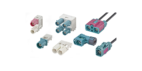
Connector types matter. SMA connectors are common for cellular and GNSS ports. FAKRA connectors are increasingly used in automotive applications because they are color-coded, keyed, and rated for higher vibration. Gold-plated center pins resist corrosion and maintain low contact resistance over time.
Ground Plane Considerations
Most fleet antennas are designed to operate with a ground plane—the metal body of the vehicle serves as the counterpoise for the antenna’s radiating element. A ground-plane-independent antenna, such as the PCTEL Smarteq AllDisc Combi, can be mounted on non-metallic surfaces (fiberglass roofs, plastic fairings) without significant performance degradation. If the mounting surface is not metal, confirm that the antenna is specified as ground-plane independent or that a suitable ground plane is provided.
Testing and Validation After Installation
After installation, validate the antenna system with the following steps:
1. GNSS fix time. With a clear sky view, the receiver should achieve a 3D fix within 30–60 seconds. If it takes longer, the antenna placement or LNA may be compromised.
2. C/N₀ (carrier-to-noise density) readings. Most modems report C/N₀ for each tracked satellite. Values above 35 dB-Hz indicate a healthy signal path; values below 25 dB-Hz suggest attenuation or interference.
3. LTE signal metrics. RSRP (Reference Signal Received Power) should be above -100 dBm in good coverage, and SINR (Signal-to-Interference-plus-Noise Ratio) should be above 10 dB.
4. Interference check. Transmit on the LTE modem at full power and observe whether GNSS C/N₀ or fix status degrades. A well-designed combo antenna should show minimal change.
Regulatory and Compliance Landscape
FCC and Carrier Certification (United States)
In the United States, a cellular modem is certified by the FCC as a complete system, including the antenna. The certification specifies a maximum antenna gain; installing an antenna with higher gain than the certified value is a violation of FCC rules and may void the modem’s certification. Fleet operators should obtain the modem manufacturer’s antenna specification sheet and confirm that the chosen antenna falls within the permitted gain range.
Carrier certification adds another layer. PTCRB (PCS Type Certification Review Board) and GCF (Global Certification Forum) certifications ensure that a device operates correctly on operator networks. Some carriers require device-level certification that includes antenna characteristics.
CE Marking and RED (European Union)
In the European Union, radio equipment must comply with the Radio Equipment Directive (RED) 2014/53/EU. The antenna itself is generally not separately certified, but the complete radio system—modem plus antenna—must meet RED essential requirements for spectrum efficiency, electromagnetic compatibility, and safety. RoHS compliance is mandatory for all electronic components, including antennas.
RoHS, REACH, and Environmental Compliance
RoHS (Restriction of Hazardous Substances) limits the use of lead, mercury, cadmium, and other hazardous materials in electrical equipment. REACH (Registration, Evaluation, Authorisation and Restriction of Chemicals) imposes additional restrictions on substances used in manufacturing. Antennas from reputable manufacturers carry RoHS and REACH declarations as standard documentation. For fleet operators with sustainability reporting requirements, these declarations support compliance with corporate environmental policies.
RF Exposure and SAR
Specific Absorption Rate (SAR) limits apply to devices held against the body. Vehicle-mounted fleet antennas are typically installed more than 20 centimeters from vehicle occupants, placing them in the “mobile device” category rather than the “portable device” category. This classification generally exempts the antenna from SAR evaluation, but the modem manufacturer’s RF exposure evaluation must account for the antenna’s gain and radiation pattern.
The Business Case: ROI and Operational Benefits of the Right Antenna
Reduced Installation and Maintenance Costs
The most immediate financial benefit of a well-chosen combo antenna is lower installation cost. A single 5-in-1 antenna replaces five separate antennas, eliminating four mounting holes, four cable runs, and four connectors. For a fleet of 500 vehicles, this reduction can translate into tens of thousands of dollars in labor savings, plus reduced vehicle downtime during installation.
Maintenance savings accumulate over the vehicle lifecycle. A sealed IP67 antenna with UV-resistant housing and vibration-rated construction has a lower failure rate than exposed connectors and adhesive-mounted pucks. Fewer antenna failures mean fewer service calls, fewer vehicle out-of-service days, and lower spare-parts inventory.
Improved Data Reliability and Operational Visibility
Antenna performance directly affects the quality of fleet data. A high-gain GNSS antenna with a low-noise LNA maintains position accuracy in urban canyons and under tree canopy, where a marginal antenna loses fix. A MIMO LTE antenna with good isolation maintains data throughput in weak-signal areas, reducing the frequency of “vehicle offline” events.
The operational consequences are significant. Dispatchers cannot route vehicles efficiently if they do not know where they are. Maintenance teams cannot schedule preventive service if they do not receive mileage and diagnostic data. Safety managers cannot coach drivers if they do not receive harsh-braking and speeding events. Each of these functions depends on a continuous, accurate data stream that begins at the antenna.
Fuel Savings and Route Optimization
Fleet telematics delivers documented fuel savings of 10–15% through route optimization, idle-time reduction, and driver behavior coaching. These savings depend on accurate position and speed data, which in turn depend on reliable GNSS reception. A vehicle that frequently loses GNSS lock cannot contribute clean data to route optimization algorithms, reducing the system’s effectiveness for the entire fleet.
Return on Investment Timeline
Telematics vendors report typical ROI timelines of 6 to 18 months for fleet tracking deployments, depending on fleet size, route complexity, and baseline fuel and maintenance costs. The antenna is a small portion of the upfront hardware cost—often less than 10%—but it protects the entire investment by ensuring that the system’s data inputs are reliable. A $50 antenna that fails after 18 months and requires a $200 service call to replace is a poor investment compared with a $100 antenna that lasts the life of the vehicle.
Future Trends in Fleet Tracking Antenna Technology
5G Sub-6 and the Expansion of MIMO
5G Sub-6 GHz deployments are expanding across fleet operating regions, offering higher throughput and lower latency than LTE. Fleet antennas are evolving to support 5G bands n77, n78, and n79 (3.3–4.2 GHz) alongside legacy LTE bands. 4x4 MIMO is becoming standard for fleet routers that support 5G, requiring antennas with four well-isolated cellular elements. The Mobile Mark LTMWG940, for example, provides four 5G/LTE MIMO elements plus GNSS in a single surface-mount housing.
L5 GNSS and Centimeter-Level Accuracy
The GNSS L5 frequency (1176 MHz) offers higher transmission power and greater resistance to multipath than L1. Dual-band L1/L5 GNSS receivers can achieve sub-meter accuracy in open-sky conditions and improved accuracy in urban environments. Some fleet applications—notably autonomous yard trucks and precision logistics—are beginning to adopt RTK (Real-Time Kinematic) positioning, which uses carrier-phase measurements to achieve 1–3 centimeter accuracy. Antennas that support L1/L5 and, in some cases, L-band correction services are positioned to serve this emerging market.
Integrated Smart Antennas and Diagnostics
The next generation of fleet antennas is adding intelligence. Some designs incorporate self-diagnostic circuitry that monitors VSWR, LNA current, and antenna presence, reporting faults to the telematics unit before they cause data loss. Others integrate eSIM or iSIM management functions, reducing the number of physical components in the system. While these features are not yet mainstream, they point toward a future in which the antenna is not just a passive RF component but an active participant in system health management.
Sustainability and Circular Design
Fleet operators are increasingly evaluated on environmental performance, and antenna manufacturers are responding with designs that use recycled materials, reduce packaging waste, and support end-of-life recycling. RoHS and REACH compliance—already standard—are being extended with product carbon footprint declarations and take-back programs. For fleets with sustainability reporting requirements, choosing antennas from manufacturers with transparent environmental documentation is becoming part of procurement policy.
Frequently Asked Questions
What is the difference between a GPS antenna and a GNSS antenna?
A GPS antenna receives signals from the United States’ GPS constellation only. A GNSS antenna receives signals from multiple constellations, including GPS, GLONASS, Galileo, BeiDou, QZSS, and NavIC. Multi-constellation reception improves position availability and accuracy, particularly in urban and obstructed environments.
Do I need a 4x4 MIMO antenna for fleet tracking?
Not necessarily. 2x2 MIMO is sufficient for most fleet tracking applications, providing a good balance of throughput and cost. 4x4 MIMO is beneficial for applications that require high data rates, such as real-time video streaming or multi-modem routers.
Can I use a magnetic-mount antenna on a fiberglass vehicle roof?
Yes, but performance will be reduced because the magnetic mount requires a metal surface to act as a ground plane. For non-metallic mounting surfaces, choose a ground-plane-independent antenna or install a separate metal ground plane beneath the antenna.
How long should a fleet tracking antenna last?
A high-quality fleet antenna with IP67 sealing, UV-resistant housing, and vibration-rated construction should last the life of the vehicle—typically 7–10 years or more. Lower-quality antennas may fail within 2–3 years, requiring replacement and service calls.
Does antenna gain affect regulatory compliance?
Yes. Cellular modems are certified with a specific maximum antenna gain. Installing an antenna with higher gain than the certified value may violate FCC rules and void the modem’s certification. Always verify that the antenna gain is within the modem manufacturer’s specified range.
What is the best mounting location for a fleet tracking antenna?
The center of the vehicle roof, with a clear view of the sky and minimal obstruction from roof racks or other antennas, is generally optimal for both GNSS and LTE performance. For temporary or leased vehicles, a magnetic-mount antenna on the roof is a practical alternative.
Fleet tracking LTE GNSS antennas are not commodities. The difference between a well-designed antenna and a marginal one is measured in missed position reports, inaccurate geofence events, intermittent connectivity, and maintenance tickets. For fleet operators, the antenna is the first link in the data chain that feeds dispatch, maintenance, safety, and customer-facing systems. Getting it right—matching frequency bands to operating regions, choosing the appropriate MIMO configuration, verifying isolation and gain specifications, and installing with proper grounding and cable routing—is the foundation of reliable fleet telematics.
The technology is evolving rapidly. 5G Sub-6, multi-constellation GNSS, L5 dual-band positioning, and intelligent diagnostics are expanding what fleet antennas can do. Fleets that invest in antennas with broad frequency coverage, robust environmental ratings, and documented regulatory compliance will be positioned to adopt these capabilities as they mature, without replacing hardware. Fleets that treat the antenna as a cost line to be minimized will continue to pay for that decision in lost data, higher maintenance costs, and reduced operational visibility.
Lucy Yang | lucy.y@toxutech.com
Dotty Zhao | sales04@toxutech.com
Global Business Director / Sales Team / Global Operations


 En
 Cn
 Korean
 Home >
