

-
Products -PCBA Manufacturing RF Connectors RF Cable Assemblys Embedded Antennas External Antennas GNSS Positioning Solutions
RF Connectors

RF Cable Assemblys
Embedded Antennas
External Antennas
GNSS Positioning Solutions



 Language


Language



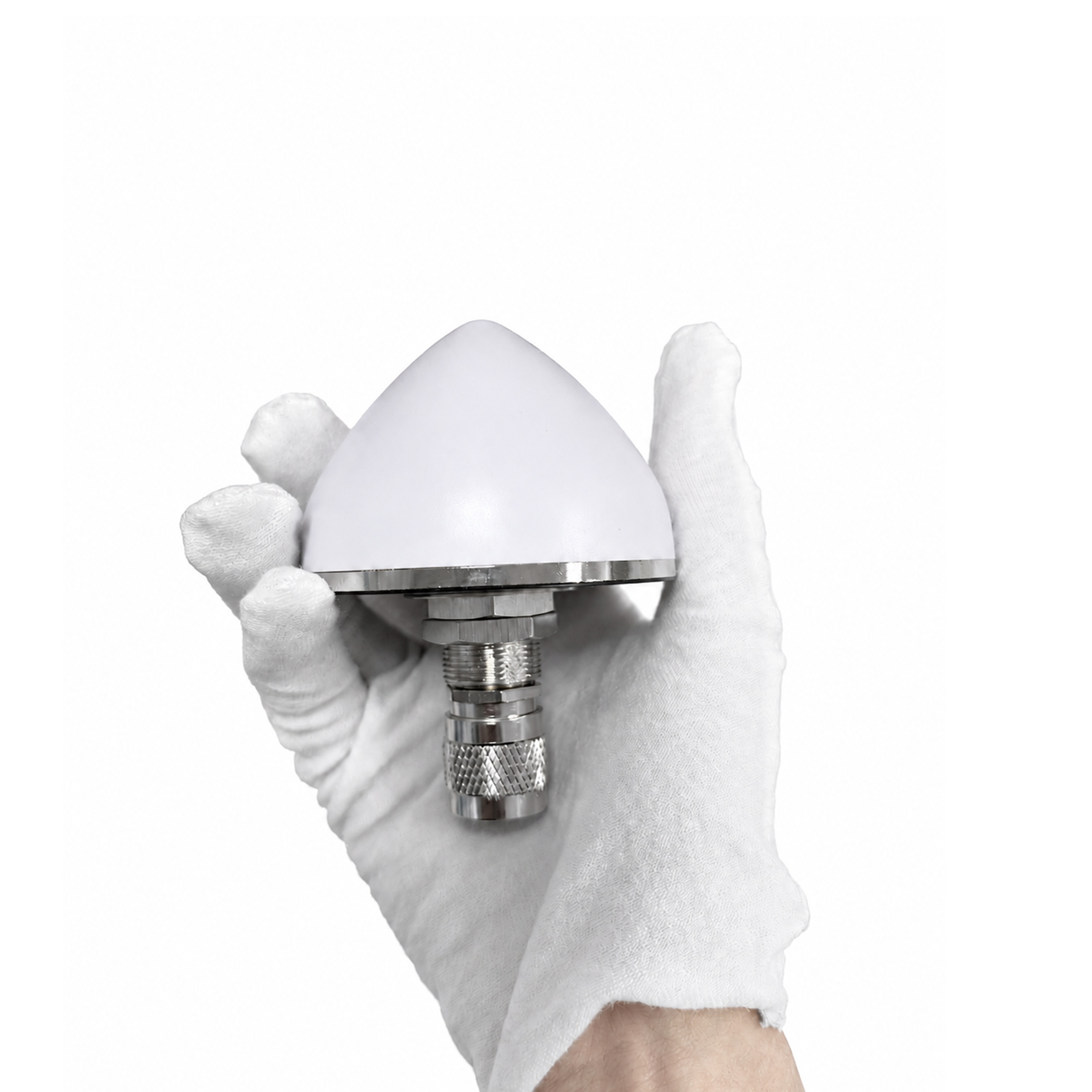
Model: KC.WA.00083
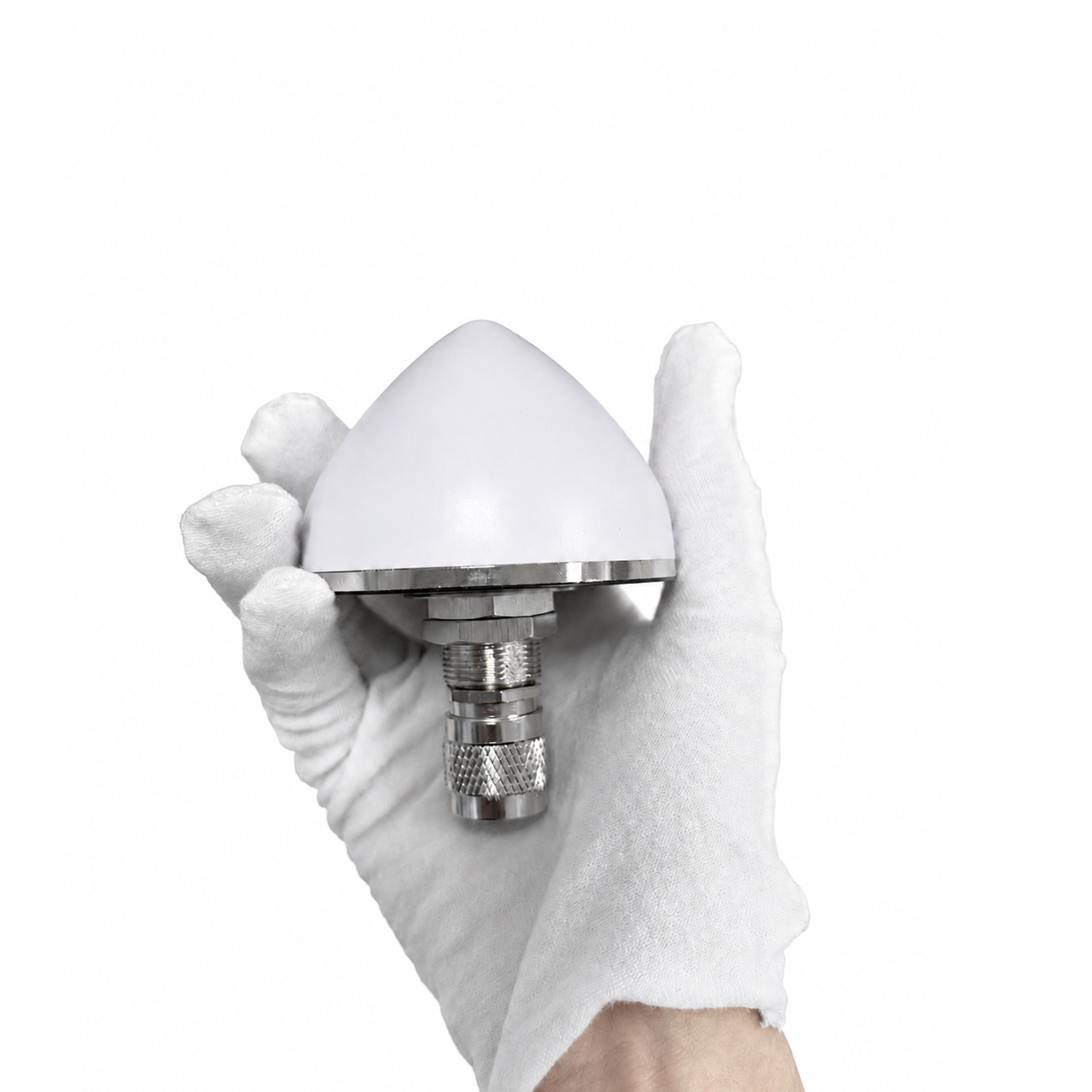
The TOXU KC.WA.00083 is an outdoor active GNSS antenna for compatible RTK receivers, positioning terminals and industrial equipment. It combines a multi-band ceramic patch with a built-in low-noise amplifier in a compact IP67 housing.
L1/L2/L5 GNSS Reception
Supports signals from GPS, BeiDou, GLONASS and Galileo at the specified operating frequencies.
40 dB Typical LNA Gain
The built-in amplifier provides 40 dB typical gain and a 2.5 dB typical noise figure.
3–12 V DC Antenna Supply
The active circuit operates from a 3–12 V DC supply with specified current consumption below 30 mA.
IP67 Housing for Outdoor Equipment
The Ø66.5 mm radome and threaded mounting stem suit outdoor GNSS equipment with limited mounting space.
RF Connector Options
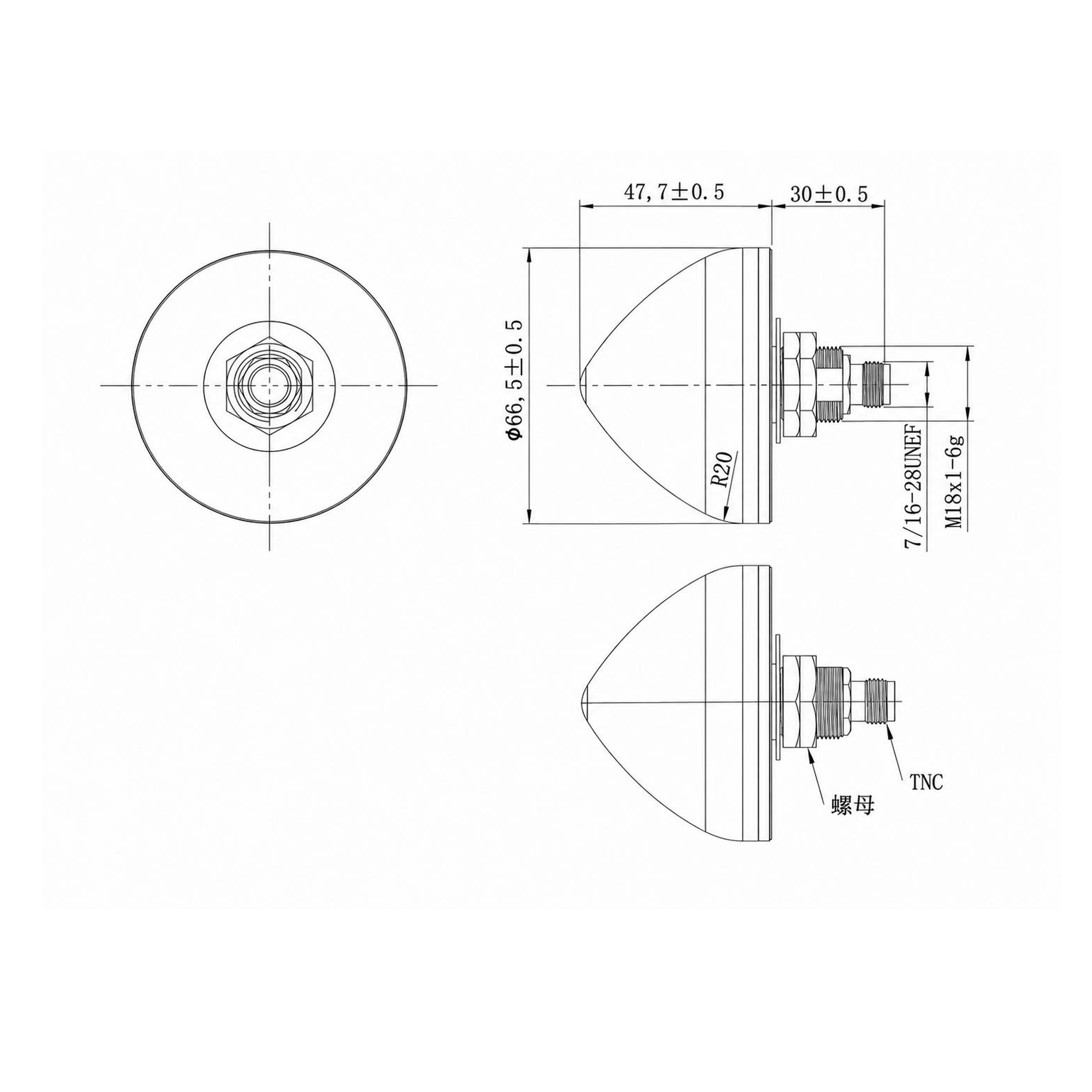
The mechanical drawing shows a TNC configuration. N male, N female and SMA options can be specified for OEM projects.
The TOXU KC.WA.00083 is an external active GNSS antenna for outdoor positioning equipment. A right-hand circularly polarized ceramic patch receives satellite signals, and a built-in low-noise amplifier boosts the received RF signal before it reaches the receiver through the coaxial connection.
The antenna is specified at 1176, 1207, 1227, 1561, 1575 and 1602 MHz for compatible GPS, BeiDou, GLONASS and Galileo reception. For RTK applications, the receiver and correction link determine which signals can be used for positioning.
The IP67 housing has a nominal diameter of 66.5 mm. The threaded mounting stem allows the antenna to sit above an equipment panel while the RF connection remains accessible from below.
Multi-Band GNSS Ceramic Patch
The ceramic element supports signals in the L1/L2/L5 groups. Its right-hand circular polarization is suited to direct GNSS satellite reception.
Low-Noise Amplifier at the Antenna
The amplifier provides 40 dB typical gain across its specified operating bands. Keeping the first amplification stage at the antenna helps offset loss in the downstream coaxial path.
Wide DC Supply Range
The 3–12 V supply range gives integrators flexibility when matching the antenna to a GNSS receiver's antenna bias or to an external bias circuit.
Outdoor Threaded Mounting
The IP67 enclosure and M18 × 1 mounting thread support fixed installation on outdoor equipment. Reserve space below the panel for the connector and cable bend.
Connector Selection for OEM Designs
Specify the connector family and mating interface when selecting the antenna. TOXU can review the connector and coaxial assembly together to suit the receiver and enclosure layout.
| Attribute | Value |
|---|---|
| Product Model | KC.WA.00083 |
| Product Type | Outdoor multi-band active GNSS antenna |
| Radiating Element | Ceramic patch |
| Supported GNSS Systems | GPS, BeiDou, GLONASS and Galileo |
| GNSS Band Groups | L1 / L2 / L5 |
| Specified Operating Frequencies | 1176, 1207, 1227, 1561, 1575 and 1602 MHz |
| Polarization | RHCP (right-hand circular polarization) |
| Ceramic Element Reflection (S11) | ≤ −12 dB (lower band) ≤ −13 dB (upper band) |
| Ceramic Element Peak Gain, Typical | 1.80 dBic at 1176 MHz 2.06 dBic at 1207 MHz 1.32 dBic at 1227 MHz 3.27 dBic at 1561 MHz 3.80 dBic at 1575 MHz 1.47 dBic at 1602 MHz |
| LNA Frequency Ranges | 1170–1230 MHz 1559–1605 MHz |
| LNA Gain | 40 dB typical |
| LNA Noise Figure | 2.5 dB typical |
| LNA Output VSWR | ≤ 2.0 |
| Supply Voltage | 3–12 V DC |
| Operating Current | < 30 mA |
| Overall Dimensions, Drawing Configuration | Ø66.5 × 77.7 mm nominal |
| Radome Dimensions | Ø66.5 ± 0.5 mm Height 47.7 ± 0.5 mm |
| Lower Interface Length, Drawing Configuration | 30 ± 0.5 mm |
| Mounting Thread | M18 × 1–6g |
| RF Connector | TNC shown in the drawing N male, N female and SMA options |
| Ingress Protection | IP67 |
| Operating Temperature | −40°C to +85°C |
| Storage Temperature | −40°C to +85°C |
| Environmental Requirement | RoHS |
The drawing shows a Ø66.5 mm radome with a 47.7 mm nominal height above the lower interface section. The M18 × 1 mounting thread and the RF connector are separate features. Use the drawing for the selected connector version when checking mounting clearance and overall height.
Outdoor GNSS and RTK Receivers
Provide external satellite reception for compatible multi-band positioning hardware.
Surveying and Mapping Equipment
Integrate an active antenna into field equipment where the antenna can be mounted above the receiver enclosure.
Precision Agriculture and Machine Guidance
Pair the antenna with compatible GNSS guidance receivers on agricultural or industrial equipment.
Industrial Positioning and Timing Terminals
Feed GNSS signals to outdoor terminals with a compatible RF input and active antenna supply.
Active GNSS antenna → RF coaxial cable → Compatible multi-band GNSS receiver
Mount the antenna with a clear view of the sky. Match the RF connector and check that the receiver's antenna bias or an external bias circuit provides the specified DC supply. Check cable loss and receiver input limits when choosing the cable length.
For RTK applications, provide compatible corrections to the receiver and evaluate the installed system under the expected satellite reception and mounting conditions.
TOXU can help select a mating RF connector and coaxial cable assembly for this antenna. Share the receiver model, cable length, mounting dimensions and required connector configuration when requesting a quote.
Antenna and Cable Selection
Review the antenna supply, RF interface and cable routing together before finalizing the equipment design.
OEM Configuration Support
Specify the connector, mounting requirements and cable assembly during sample evaluation to establish the configuration for repeat orders.
TOXU Tech supplies GNSS and communication antennas, RF connectors, coaxial cable assemblies and GNSS positioning hardware for equipment manufacturers and system integrators.
TOXU also provides PCBA manufacturing and OEM / ODM integration support for RF and GNSS hardware projects.
Which GNSS systems and bands are supported?
The antenna supports GPS, BeiDou, GLONASS and Galileo signals within the frequencies listed in the specifications. Match these frequencies to the signals used by your receiver.
What does the 40 dB figure refer to?
40 dB is the typical gain of the built-in LNA. The ceramic element's peak gain is listed separately in dBic at each specified frequency.
How is the active antenna powered?
The antenna requires 3–12 V DC. Check the receiver's antenna bias voltage and available current, or use a compatible external bias circuit.
Can it be used with an RTK receiver?
Yes. Match the receiver's GNSS bands, antenna supply and RF connection. RTK positioning performance also depends on correction data, receiver settings and satellite reception.
Which connector configurations are available?
The drawing shows a TNC configuration. N male, N female and SMA options can be specified according to the required mating interface.
Can the antenna be installed outdoors?
The antenna housing is specified to IP67. Use the appropriate connector sealing and panel installation for the selected configuration.
Lucy Yang | lucy.y@toxutech.com
Dotty Zhao | sales04@toxutech.com
Global Business Director / Sales Team / Global Operations


 En
 Cn
 Korean
 Home >


